
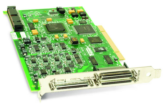
Quanser QPID
The Quanser QPID is an innovative H.I.L. control board with an extensive range of input and output support. A wide variety of devices with analog and digital sensors as well as quadrature encoders are easily connected to the Quanser QPID. This single-board solution is ideal for use in control systems and complex measurement applications.
 This card is no longer available. For a newer card with similar capabilities, visit the
Quanser DAQ website.
This card is no longer available. For a newer card with similar capabilities, visit the
Quanser DAQ website.
The QUARC driver name for this card is qpid .
The features of the Quanser QPID card are:
This single board integration enables you to turn your PC into a powerful Desktop Control Station.
 If you are using a Quanser QPIDe board, attach a standard ATX (Advanced Technology Extended) peripheral power connector to the board. If the ATX
connection is not attached on the QPIDe board, only limited power will be available and the encoder may not be properly powered. This may also
result in damage to the board.
If you are using a Quanser QPIDe board, attach a standard ATX (Advanced Technology Extended) peripheral power connector to the board. If the ATX
connection is not attached on the QPIDe board, only limited power will be available and the encoder may not be properly powered. This may also
result in damage to the board.
Communications
For SPI support, refer to the spi communication protocol available through the Quanser Stream API and Stream blockset in Simulink, or at the card-specific protocols spi-qpid or spi-qpid_e.
Clocks
The Quanser QPID supports seventeen hardware "clocks", as well as one system timer. The system timer has 1ms resolution. Most of the hardware "clocks" are actually external interrupt sources. The following paragraphs describe each of the hardware clocks available.
The most commonly used hardware clock is the "General purpose 24-bit counter (COUNTER)" or HARDWARE_CLOCK_0 (0).
This clock is a 24-bit counter with 25 nanosecond resolution (40 MHz). This clock is generally used as a hardware
timebase using one of the HIL Timebase blocks. Through the board-specific options, this clock may be also used to
trigger A/D conversions in hardware or synchronize more than one QPID card through the RTSI interface.
The Quanser QPID also provides another 24-bit counter called the "Watchdog 24-bit counter (WATCHDOG)" or HARDWARE_CLOCK_1 (1).
It also has a 25 nanosecond resolution (40 MHz). This clock is used as the watchdog timer when a
HIL Watchdog block is present in the diagram.
If it is not being used as a watchdog timer, this clock may be used as a general purpose timebase.
There are two smaller counters that may be also used as general purpose timebases: "Small 16-bit counter 0" or HARDWARE_CLOCK_2 (2)
and "Small 16-bit counter 1" or HARDWARE_CLOCK_3 (3). These counters are 16 bits and use a 1.25MHz timebase.
Hence, valid clock frequencies range from 1.25MHz to approximately 19.1Hz.
The next counter is interesting because it is the same counter used for the PWM outputs. The "PWM period"
counter or HARDWARE_CLOCK_4 (4) may be used as a hardware timebase. This counter is shared by all eight
PWM outputs and determines the period of the PWM pulses (not the duty cycle). By using this counter as a
hardware timebase for the model, it is possible to synchronize the model to the PWM outputs! The counter
interrupt occurs on the leading edge of the PWM period, so how the interrupt is synchronized to the PWM
output pulses depends on the alignment settings for the PWM outputs. Refer to the PWM output section below
or the PWM Output Configurations page
for details.
Hardware clocks 5 through 12 (HARWARE_CLOCK_5 through HARDWARE_CLOCK_12) correspond to
digital inputs 0 to 7. A rising edge on the corresponding digital input will cause an interrupt and
this interrupt may be used to drive the sampling rate of the model via the corresponding hardware clock.
Thus, external signals may be used to drive the sampling rate of the model via these digital I/O lines.
The next hardware clock, HARDWARE_CLOCK_13, is the FUSE line. The FUSE line monitors
the state of the three fuses on the QPID terminal board. It is not accessible as an external input unless
the terminal board is not used. This clock source should not be used as a hardware timebase and is intended
as an interrupt source instead. The polarity of the FUSE line may be set through the board-specific
options.
The last three hardware clocks, HARDWARE_CLOCK_14 through HARDWARE_CLOCK_16, correspond to
the EXT_INT, CONVERT and TRIG0 inputs respectively. The EXT_INT and
CONVERT signals are input pins available on the QPID terminal board's Control header. The TRIG0
input is available on the RTSI connector on the Quanser QPID card itself, and may be used to synchronize multiple
QPID cards. All three clocks allow an external input to be used as a clock source, much like the first eight
digital I/O lines. The polarity of the EXT_INT and CONVERT inputs may be set through
the board-specific options.
To synchronize multiple QPID cards to the hardware timebase on one card, set up the "master" card to use
HARDARE_CLOCK_0 as its hardware timebase. Also set the counter_to_trig0 option to "yes" so
that the clock pulse appears on the RTSI TRIG0 pin of the "master" card as an output. Then configure all
the "slave" cards to use HARDWARE_CLOCK_16 (the RTSI TRIG0 pin) as their hardware timebase.
Do not configure the counter_to_trig0 option on the slave cards! Finally, wire
the RTSI TRIG0 pins of the master and slaves together.
Analog Inputs
The Quanser QPID supports eight 16-bit differential analog inputs with a ±10V range. Hence analog channel numbers range from 0 to 7.
Since the range of the analog inputs is fixed at ±10V, there is no need to configure the analog input ranges.
The analog inputs measured using a single HIL Read block will be sampled simultaneously. All eight analog inputs may be sampled simultaneously by reading all eight channels with a single HIL Read block.
Analog Outputs
The Quanser QPID supports eight 16-bit single-ended analog outputs with a programmable range. As there are eight outputs, analog channel numbers range from 0 to 7.
In order to have analog outputs set to a particular voltage when the model is loaded
or unloaded, the analog outputs must be configured on the
HIL Initialize
block's Analog Outputs
tab. Set the Analog output channels field to
all the analog output channels that will be used on the board for the current diagram.
For example, enter 1:3 to indicate channels 1 through 3. Specify
[0, 2, 7]
to indicate channels 0, 2 and 7.
Set the Initial analog outputs and Final analog outputs to the desired voltages. If the vectors specified in these fields are shorter than the channel vector, the value of the last element in the vector will be used for the rest of the channels. Hence, a scalar value will apply to all channels specified in the Analog output channels field.
The first four analog output channels are dual purpose. When the PWM output channels are configured in bipolar mode, these analog output channels are driven with bipolar PWM output signals. The amplitude of these output signals may be controlled by writing to the corresponding analog outputs. For more information, refer to the description of the PWM outputs below.
Digital Inputs
The Quanser QPID supports 56 bidirectional digital I/O lines and four special digital input lines.
Hence digital input channel numbers range from 0 to 59. Channels 56
through 59 are FUSE, EXT_INT, CONVERT
and TRIG0 respectively. A digital I/O line cannot be used as an input and output at the same
time.
Since the first 56 digital I/O lines may be individually programmed as inputs or
outputs on the Quanser QPID, all of those 56 channels which will be used
for digital inputs should be configured on the HIL Initialize
block's Digital Inputs tab. Set the Digital input channels field to all
the digital I/O channels that will be used as digital inputs on the board for the current diagram. For example, enter
3:15 to designate channels 3 through 15 as digital inputs. Specify
[0, 4, 5] to indicate that channels 0, 4 and 5 are to be configured
as digital inputs.
The FUSE input reflects the status of the fuses on the QPID terminal board. The QPID
terminal board has one fuse for each of the three cables going to the terminal board, since each cable supplies
its own power to the board. If any one of these fuses blows then the FUSE input will
go low. Under normal operation, this input is high.
The EXT_INT input reads the value of the external interrupt pin (EXT_INT) on the Control header
of the QPID terminal board. This pin may be used as an external clock for driving the model as a hardware timebase,
but it may also be read as a simple digital input.
The CONVERT input reads the value of the A/D Convert pin (CONVERT) on the Control header
of the QPID terminal board. This pin may be used as an external clock for driving the model as a hardware timebase
as well, triggering A/D conversions directly, but it may also be read as a simple digital input.
The TRIG0 input reads the value of the TRIG0 pin on the RTSI header directly on
the QPID card itself. This pin may be used as an external clock for driving the model as a hardware timebase,
in order to synchronize multiple QPID cards. However, it may also be read as a simple digital input.
Digital inputs 0-31 are sampled simultaneously when measured using a single HIL Read block. All 32 digital inputs may be sampled simultaneously by reading all 32 channels with a single HIL Read block.
Likewise, digital inputs 32-55 are sampled simultaneously when measured using a single HIL Read block.
Digital Outputs
The Quanser QPID supports 56 bidirectional digital I/O lines. Hence digital output channel numbers range from 0 to 55. A digital I/O line cannot be used as an input and output at the same time.
Since the first 56 digital I/O lines may be individually programmed as inputs or outputs
on the Quanser QPID, all the channels which will be used for digital outputs should be configured
on the HIL Initialize block's
Digital Outputs tab. Set the Digital output channels
field to all the digital I/O channels that will
be used as digital outputs on the board for the current diagram. For example, enter
3:15 to designate channels 3 through 15 as digital outputs. Specify
[0, 4, 5] to indicate that channels 0, 4 and 5 are to be configured
as digital outputs.
To set the digital output values when the model is loaded or unloaded, set the Initial digital outputs and Final digital outputs parameters to the desired values respectively. If the vectors specified in these fields are shorter than the channel vector, the value of the last element in the vector will be used for the rest of the channels. Hence, a scalar value will apply to all channels specified in the Digital output channels field.
| Each digital output can source up to 5mA of current maximum, with a total of 75mA maximum for each set of eight channels (0-7, 8-15, etc). Do not exceed these maximums! |
Digital outputs 0-31 are updated simultaneously when written using a single HIL Write block. All 32 digital outputs may be updated simultaneously by writing all 32 channels with a single HIL Write block.
Likewise, digital outputs 32-55 are updated simultaneously when written using a single HIL Write block.
Encoder Inputs
The Quanser QPID supports eight quadrature encoder inputs with 24-bit count values. Hence encoder channel numbers range from 0 to 7.
In order to set the encoder counters to a particular count or to change the default
quadrature or filter frequency when the model is loaded, the encoder inputs must
be configured on the HIL Initialize
block's Encoder Inputs tab. Set the Encoder input channels
field to all the encoder channels that will be
used on the board for the current diagram. For example, enter
2:7
to
indicate channels 3 through 7 are used as encoder inputs. Specify
[0, 2, 7]
to indicate that channels 0, 2 and 7 are used as encoder inputs.
The Quanser QPID supports non-quadrature (count and direction) and 4X quadrature. The Quanser QPID
supports filter frequencies of 40e6/N
where N=1..32. In other words, valid Quanser QPID filter frequencies range from
1.25MHz to 40MHz. Since the Quanser QPID has 24-bit counters, valid initial count values range
from -8,388,608 to +8,388,607.
If the vectors specified in these fields are shorter than the channel vector, the value of the last element in the vector will be used for the rest of the channels. Hence, a scalar value will apply to all channels specified in the Encoder input channels field.
To synchronize sampling of the encoders with A/D conversions, set the "Latch encoders on an A/D conversion" option in the board-specific options. When this option is selected, the analog inputs and encoder inputs are together sampled simultaneously.
The direction of any encoder channel may be reversed via the board-specific enc<n>_dir
options. The ability to reverse the direction in which the encoder counts is convenient when connecting
to hardware because it obviates the need for confusing sign changes in code.
The Quanser QPID also supports measurement of the encoder velocities in hardware. The encoder velocity measurements provide velocity information with no differentiation required. The velocities generally have higher resolution than those obtained by differentiation, particularly at slow velocities, and can provide instantaneous velocities. Refer to the "other input channels" below for more details!
Note that the QPID provides encoder velocities based on the rising edge of the A signal only. The measurements
are therefore 1X quadrature, not full, 4X, quadrature. The velocities measured are very accurate but may have
phase delays that are velocity dependent due to the lack of full quadrature support. For full quadrature velocity
measurements the PCI Express QPIDe card is required.
The Quanser QPID provides support for the index pulse on each encoder channel. The encoder count values when the last index pulses occurred are available as additional outputs. Refer to "output input channels" below for details.
The encoder counters may also be programmed to reload from the initial value when an index pulse
occurs. Set the appropriate enc<n>_reload flag in the board-specific options to enable
this feature. However, for control purposes, it is probably better to look for changes in the most recent
index position as reported by the other input channels than to have the actual encoder counts change
asynchronously with respect to the software.
The index pulse is detected when the A, B and Z signals of the encoder have a particular polarity. The polarity of each of these signals used to detect an index pulse is programmed through the board-specific options (see below). Doing so typically allows the index position to be determined with full quadrature accuracy. If the other input channels reflecting the position of the last index pulse continuously change as the encoder is rotated then the polarity of Z is likely incorrect.
Encoder inputs are sampled simultaneously when measured using a single HIL Read block. All eight encoder inputs may be sampled simultaneously by reading all eight channels with a single HIL Read block.
Furthermore, the encoder positions, index positions and velocities are all sampled together simultaneously (in hardware) when measured using a single HIL Read block. This functionality is very useful for complex mechanical devices in which it is important to know the joint angles and velocities at a particular instant in time because small errors in these quantities could lead to inaccurate kinematic calculations. Without simultaneous sampling the mechanical system could not be guaranteed to be in exactly the same position when the different joint angles and velocities were measured.
PWM Outputs
The Quanser QPID driver supports eight PWM output channels. The PWM outputs appear on their own PWM header on the QPID terminal board.
These eight channels are all driven by one timebase, but their duty cycles may be independently controlled. It is possible to synchronize the execution of a model to this PWM timebase by using it as a hardware timebase. Refer to the section on Clocks above.
The PWM output channels support a broad variety of options and are extremely flexible. They are suitable for a number of applications, including more specialized applications such as three-phase motor control, driving RC servos, H-bridges and inverters, pulse generation and more.
Each output channel can be programmed with a duty cycle ranging from 0 to 100% inclusive. Since the outputs can be set to be fully low (0%) or high (100%), they can also serve as additional digital outputs if necessary.
The output pulse may be aligned at the beginning of the PWM period (leading alignment), center of the PWM period (center alignment) or at the end of the PWM period (trailing alignment).
Channels can be coordinated so that the output pulses of pairs of channels are synchronized or complementary. Most importantly, independent leading and trailing edge deadband may be inserted between the coordinated outputs so that H-bridges may be driven without large current spikes.
PWM outputs can be configured in "one-shot" mode, which allows greater resolution when driving RC servos. In one-shot mode, the PWM output pulses only occur once each time the PWM outputs are written. Hence, PWM output pulses may be generated less frequently, while still maintaining high resolution in the width of the duty cycle.
This mode is particularly well suited for RC servos, where the time between pulses is long but the width of the pulse is much narrower. For example, RC servos typically require a pulse every 20ms. However, the pulse width itself may vary only between 1ms and 2ms to get the full-scale range of the RC servo. Using a PWM period of 20ms would waste much of the resolution of the PWM output on the 18ms of the period that are never used. One-shot mode, however, allows a PWM period of 2ms to be employed so that more of the resolution of the PWM output is available to produce the 1ms to 2ms pulse. An independent timebase may then be used to generate the 20ms period.
By default, changes to the PWM duty cycle via the HIL PWM Output block or hil_write_pwm_outputs function are synchronized to the PWM period. This synchronization ensures that the transition between duty cycles is smooth. However, for some applications it is better to update the PWM duty cycle immediately, even in the middle of a PWM period. In this case, the output that occurs for the PWM period during the transition depends upon the different PWM options. To force the PWM outputs to update immediately set the Update PWM outputs immediately (asynchronously) option in the board-specific options (see below).
For a complete description of all the options available, including diagrams, refer to PWM Output Configurations .
The PWM outputs are updated simultaneously when written using a single HIL Write block. All eight PWM outputs may be updated simultaneously by writing all 32 channels with a single HIL Write block.
Other Inputs
The Quanser QPID supports 17 other input channels. Other input channel numbers are assigned according to functionality rather than sequentially in QUARC, so that boards from more than one manufacturer still use the same other input channel numbers for the same functionality. This scheme makes it easier to exchange boards from different manufacturers. Refer to QUARC Other Channels for a list of the Other Input or Output channel number ranges defined for any HIL Data Acquisition Card and their SI units.
Other input channel 10000 reflects the temperature of the Quanser QPID card measured by the on-board temperature sensor. Its units are degrees Celcius and it has a 0.25 degree resolution.
Other input channels 13000 through 13007 reflect the positions of the most recently encountered encoder index pulses for encoder inputs 0 through 7 respectively. The values are in counts. These inputs are useful for determining where the index positions are located on the encoders.
Other input channels 14000 through 14007 are hardware velocity measurements for encoder inputs 0 through 7 respectively, in counts per second. These measurements are independent of the sample rate of the model and are unaffected by sample rate jitter. They reflect the instantaneous velocity of the encoder channel.
The fastest resolvable velocity is equal to the encoder filter frequency (maximum 40 million counts per second).
The slowest measurable velocity (besides zero) is equal to Fs / 16777214,
where Fs is the encoder filter frequency. For a 40 MHz filter frequency,
the slowest resolvable velocity is approximately 2.4 counts per second.
An artificial minimum velocity may be set in the card-specific options if friction is known to stop the device before the slowest measurable velocity is reached. See the card-specific options below for details.
The channels related to the encoders are all sampled simultaneously when measured using a single HIL Read block.
Other Outputs
The Quanser QPID card does not support other outputs.
Interrupts
The Quanser QPID supports 29 different interrupt sources from a variety of its inputs. There are digital interrupts, analog interrupts, encoder interrupts and timer interrupts.
Digital input interrupts
The first eight digital inputs are capable of generating an interrupt on either the rising edge or the falling edge of the digital input. The falling edge is used to trigger an interrupt by default, but the polarity may be changed using the d0_polarity through d7_polarity board-specific options. Use interrupt channels 0 through 7 to respond to these interrupts.
Fuse interrupt
The fuse input may generate an interrupt on a rising or falling edge. The falling edge is used to trigger an interrupt by default, but the polarity may be changed using the fuse_polarity board-specific option. Use interrupt channel 8 to respond to this interrupt.
External interrupt (EXT_INT) interrupt
This interrupt is generated when a rising or falling edge appears on the EXT_INT pin on the Control header. The falling edge is used to trigger an interrupt by default, but the polarity may be changed using the ext_int_polarity board-specific option. Use interrupt channel 9 to respond to this interrupt.
A/D conversion trigger (CONVERT) interrupt
This interrupt is generated when a rising or falling edge appears on the CONVERT pin on the Control header. The falling edge is used to trigger an interrupt by default, but the polarity may be changed using the convert_polarity board-specific option. Use interrupt channel 10 to respond to this interrupt.
RTSI trigger 0 interrupt
This interrupt is generated when a rising edge appears on the TRIG0 pin on the RTSI header. Use interrupt channel 11 to respond to this interrupt.
Encoder index pulse interrupts
Each encoder channel is capable of generating an interrupt when the index pulse is seen. There is a separate interrupt for each encoder channel. The polarity of the A, B and Z signals required to recognize an index pulse may be configured via the enc0_a, enc0_b, enc0_z and similar board-specific options. Use interrupt channels 1000-1007 to respond to these interrupts for encoder channels 0-7 respectively.
Analog threshold interrupts
The first four analog input channels are capable of generating an interrupt when the analog input falls below a minimum threshold or rises above a maximum threshold. There is a separate interrupt for each analog channel. The analog thresholds for all four channels may be configured via the analog_min and analog_max board-specific options. Use interrupt channels 2000-2003 to respond to these interrupts for analog channels 0-3 respectively.
 The analog threshold interrupts are only active when the board is configured to perform A/D conversions, since the
threshold comparison is done digitally in the hardware. To configure the card to perform A/D conversions automatically,
set the trigger_adcs option to
The analog threshold interrupts are only active when the board is configured to perform A/D conversions, since the
threshold comparison is done digitally in the hardware. To configure the card to perform A/D conversions automatically,
set the trigger_adcs option to yes or 1 in the board-specific options. Then program
the COUNTER timebase i.e., HARDWARE_CLOCK_0 (0), with the frequency at which A/D conversions should be triggered using
the hil_set_clock_frequency function or the Initial clock frequencies
parameter of the HIL Initialize block.
General purpose (24-bit) counter (COUNTER) interrupt
This interrupt is generated each time the 24-bit general purpose counter (COUNTER) expires.
Watchdog (24-bit) counter (WATCHDOG) interrupt
This interrupt is generated each time the 24-bit watchdog counter (WATCHDOG) expires.
Small 16-bit counter 0 interrupt
This interrupt is generated each time the small 16-bit counter 0 expires.
Small 16-bit counter 1 interrupt
This interrupt is generated each time the small 16-bit counter 1 expires.
PWM period interrupt
This interrupt is generated at the beginning of each PWM period. It can be useful for synchronizing operations to the PWM period when the sample time of the model is different from the PWM period.
Watchdog
The Quanser QPID supports the use of the 24-bit general purpose clock, WATCHDOG,
as a watchdog timer. The timer may be programmed with any interval between 25 ns and 419 ms. The board is capable
of resetting the analog outputs, digital outputs and PWM outputs to any state upon expiration of the watchdog
timer. Resetting of the outputs occurs without
software intervention, and therefore may be used as a safety mechanism in the event of software
failure.
To enable the resetting of the analog, digital or PWM outputs, check the Set analog outputs at watchdog expiration, Set digital outputs on watchdog expiration or Set PWM outputs on watchdog expiration options in the HIL Initialize block parameters. Set the analog, digital and PWM output values on watchdog expiration to the desired values. Then place a HIL Watchdog block in the diagram.
When the watchdog functionality is used, the WDOG pin will reflect the status of the
watchdog timer (or other watchdog source). The WDOG pin may be found on the CONTROL header
on the Quanser QPID terminal board. This pin is normally high. If the watchdog timer is allowed to
expire, then this pin will go low. This polarity may be reversed through the board-specific options. Changing the
WDOG pin polarity does not change the polarity of the return value from
the hil_watchdog_reload function or the
Note that the WDOG pin will only reflect the status of the watchdog timer (or other watchdog source)
when at least one of the analog, digital or PWM outputs has been configured to have its state set on
watchdog expiry. If none of the outputs are configured to be set on watchdog expiry then the WDOG pin
will not change on watchdog expiry.
Once the watchdog has expired, further I/O is disabled until the watchdog state is cleared. The WDOG pin remains low after expiration until the watchdog is restarted.
Hence, in Simulink models, the WDOG pin will remain low after watchdog expiration even after the model is stopped, unless a HIL Watchdog Clear block is used to clear the watchdog state. Restarting the model causes the WDOG pin to go high once more. These semantics make the WDOG pin useful for ensuring product safety.
The fuse on the Quanser QPID terminal board may also be configured to act as a watchdog through the
board-specific options. In this case, the model or application should be stopped and only restarted
once the fuse has been replaced. The state of the FUSE line may be monitored using digital
input channel 56. The polarity of the FUSE line may be reversed through the board-specific
options. However, changing its polarity is not recommended when using a QPID terminal board, since
the FUSE line is hard-wired to monitor the three fuses on the terminal board.
The EXT_INT pin on the Control header of the QPID terminal board may also be used as a watchdog. This feature is useful for integrating the QPID into external emergency stop circuitry so that the board's outputs are reset as soon as the emergency stop is engaged, without software intervention. The polarity of the EXT_INT line may be reversed through the board-specific options.
Finally, the RTSI TRIG1 pin may also be used as a watchdog trigger. This pin is available
on the RTSI connector of the QPID card itself. This feature is enabled through the board-specific
options and allows the watchdog state of multiple QPID cards to be synchronized. For example,
to synchronize the watchdog state of three QPID cards in the same PC, set the trig1_watchdog
and watchdog_to_trig2 options of each card to "yes". If card #0 is to be the "master", then
wire the RTSI TRIG2 pin of card #0 to the RTSI TRIG1 pin of card #1. Daisy-chain
the next card by wiring RTSI TRIG2 of card #1 to the RTSI TRIG1 pin of card #2. Then
if card #0 goes into the watchdog state (due to watchdog timer expiration, a fuse blowing, and/or an
external watchdog, according to its board-specific options) then card #1 and card #2 will also go
into the watchdog state.
As already alluded, it is possible to route the watchdog state to the RTSI pins through the board-specific
options. The watchdog state may be routed to the RTSI TRIG1 and/or TRIG2 pins. It always
appears at the WDOG output.
Board-Specific Options
The QPID has a number of board-specific options to control specialized functionality of the card. These options control the polarity of certain inputs to the card, determine the watchdog and general-purpose counter functionality, and configure the PWM output semantics.
The checkboxes on the board-specific dialog generally have three states: with a checkmark, with no checkmark and filled with a solid box. When there is a checkmark, the option is set to the 'on' state, and when there is no checkmark (the box is empty), the option is set to the 'off' state. When the box is filled with solid colour then the option is not set at all, but is left in its current state. This "indeterminate" state is useful when more than one model is being used to access the same hardware, and there is a desire to have a model not interfere with the settings configured by another model.
convert_polarity
This option reverses the polarity of the CONVERT input pin. The CONVERT line is active-low (0)
by default, but setting the convert_polarity option to 1 causes it to be active-high.
ext_int_polarity
This option reverses the polarity of the EXT_INT input pin. The EXT_INT line is active-low (0)
by default, but setting the ext_int_polarity option to 1 causes it to be active-high.
fuse_polarity
This option reverses the polarity of the FUSE input. The FUSE line is active-low (0)
by default, but setting the fuse_polarity option to 1 causes it to be active-high.
| Do not use this option if you are using a QPID terminal board! |
watchdog_polarity
This option reverses the polarity of the WDOG output pin of the card. The WDOG line is active-low (0)
by default, but setting the watchdog_polarity option to 1 causes it to be active-high.
Note that changing the WDOG pin polarity does not change the polarity of the return value from
the hil_watchdog_reload function or the
d0_polarity
This option reverses the polarity of the digital input #0 pin with respect to interrupts. The digital input
generates an interrupt on a high-to-low transition (0) by default, but setting this option to 1
causes it to generate an interrupt on a low-to-high (1) transition.
Similar options exist for the first eight digital input channels e.g. d1_polarity, ..., d7_polarity.
ext_int_watchdog
Set this option to "yes", "y" or "1" to use the EXT_INT input pin as a watchdog source. A falling
edge (or rising edge if ext_int_polarity is "1") on this input will then cause the card to reset all
its outputs to the assigned values and to enter a watchdog state.
The EXT_INT pin is not used as a watchdog if this option is not set.
fuse_watchdog
Set this option to "yes", "y" or "1" to use the FUSE input pin as a watchdog source. A falling
edge (or rising edge if fuse_polarity is "1") on this input will then cause the card to reset all
its outputs to the assigned values and to enter a watchdog state.
The FUSE pin is not used as a watchdog if this option is not set. This option is highly recommended
when using the QPID terminal board because the encoders are powered from the board. If the fuse blows or
even degrades, then this option can be crucial in stopping a controller that is rapidly increasing its
output torque (due to an integral term) because the encoders are not working and the controller is
trying to get the apparatus to move!
trig1_watchdog
Set this option to "yes", "y" or "1" to use the RTSI TRIG1 input pin as a watchdog source. A falling
edge on this input will then cause the card to reset all its outputs to the assigned values and to enter
a watchdog state.
The TRIG1 pin is not used as a watchdog if this option is not set. This option is typically used
to daisy-chain QPID card together so that the watchdog on one card can trigger the watchdog operation
of the next card in the chain. See the watchdog_to_trig1 and watchdog_to_trig2 options
below.
watchdog_to_trig1
Set this option to "yes", "y" or "1" to output the watchdog state on the RTSI TRIG1 pin.
This pin may then be wired to another card's RTSI header to pass this information on to another
card, and possibly trigger a watchdog operation on that card. The pin goes low when the watchdog
expires.
watchdog_to_trig2
Set this option to "yes", "y" or "1" to output the watchdog state on the RTSI TRIG2 pin.
This pin may then be wired to another card's RTSI header to pass this information on to another
card, and possibly trigger a watchdog operation on that card. The pin goes low when the watchdog
expires.
trigger_adcs
Set this option to "yes", "y" or "1" causes the general-purpose counter, COUNTER, to
trigger A/D conversions directly on the QPID card. Thus, when a HIL Read Analog Timebase
or HIL Read Timebase block is used in a model with analog input channels
and the HARDWARE_CLOCK_0 (COUNTER) as a hardware timebase, then the A/D conversions are
guaranteed to be performed at the exact sampling interval programmed for the model. This option
not only helps to reduce jitter in the analog measurements, but it is also more efficient because
it overlaps the A/D conversions and the interrupt latency of the PC.
counter_to_trig0
Set this option to "yes", "y" or "1" to output a pulse to the RTSI TRIG0 pin every time
the general-purpose counter, COUNTER, expires. This option may be used to synchronize
multiple cards to the hardware timebase of a "master" QPID card. It is particularly useful when
combined with the trigger_adcs option because it allows A/D conversions on multiple
cards to be synchronized.
latch_on_adc
Set this option to "yes", "y" or "1" to latch the encoder inputs, index positions and velocities at the same time as A/D conversions. This option is useful for simultaneously sampling the analog and encoder inputs together when such precision is necessary.
pwm_immediate
Set this option to "yes", "y" or "1" to update PWM outputs as soon as a value is written to one of the PWM channels. Normally, the changes in the duty cycle of the PWM outputs are synchronized to the beginning of the PWM period to avoid glitches in the PWM outputs. Setting this option to "yes" causes the outputs to be updated immediately, even if it means producing a second pulse within the same PWM period. For example, when using trailing edge alignment, switching from a 90% duty cycle to a 10% duty cycle near the middle of the PWM period could cause the 90% duty cycle to be truncated immediately and then restarted near the end of the PWM period to generate the 10% duty cycle pulse. Some systems, however, do perform better when the PWM outputs are updated immediately, so this option is provided.
enc0_dir
Set this option to "yes", "y" or "1" to reverse the direction of encoder 0. This feature makes it easier to migrate to the Quanser QPID hardware from another data acquisition card. It also allows models to be more portable to other cards.
Similar options exist for the other encoder channels e.g. enc1_dir, enc2_dir, etc.
enc0_filter
Set this option to "yes", "y" or "1" to enable filtering on encoder channel 0. The Quanser QPID filtering oversamples the A, B and Z channels are tries to eliminate spurious glitches in the inputs. However, use of filtering slows down the maximum encoder velocity that may be measured.
Similar options exist for the other encoder channels e.g. enc1_filter, enc2_filter, etc.
enc0_a
This option determine the state of the A signal required for an index pulse to be recognized. Set this option to "yes", "y" or "1" to require that the A signal be high for an index pulse to be detected. Set it to "no", "n" or "0" to require the A signal to be low. If a Quanser QPID terminal board is being used, then these polarities are reversed because the buffers on the terminal board are inverting. In that case, select "1" to require that A is low, and "0" to require that it be high.
Similar options exist for the other encoder channels e.g. enc1_a, enc2_a, etc.
enc0_b
This option determine the state of the B signal required for an index pulse to be recognized. Set this option to "yes", "y" or "1" to require that the B signal be high for an index pulse to be detected. Set it to "no", "n" or "0" to require the B signal to be low. If a Quanser QPID terminal board is being used, then these polarities are reversed because the buffers on the terminal board are inverting. In that case, select "1" to require that B is low, and "0" to require that it be high.
Similar options exist for the other encoder channels e.g. enc1_b, enc2_b, etc.
enc0_z
This option determine the state of the Z signal required for an index pulse to be recognized. Set this option to "yes", "y" or "1" to require that the Z signal be high for an index pulse to be detected. Set it to "no", "n" or "0" to require the Z signal to be low. If a Quanser QPID terminal board is being used, then these polarities are reversed because the buffers on the terminal board are inverting. In that case, select "1" to require that Z is low, and "0" to require that it be high.
Similar options exist for the other encoder channels e.g. enc1_z, enc2_z, etc.
If this option is set incorrectly then an index pulse is detected every time the A and B signals match the criteria defined
by the enc0_a and enc0_b options - which is basically "all" the time. If the index
position vary seemingly continuously, try changing this option to the opposite polarity.
enc0_reload
Set this option to "yes", "y" or "1" to reload encoder counter 0 when the index pulse occurs. This option is generally not recommended because it wreaks havoc on controllers if the controller is not carefully designed. The Quanser QPID keeps track of the last position at which an index pulse occurred in a separate set of registers, so reloading the encoder counter on an index pulse is less important.
Similar options exist for the other encoder channels e.g. enc1_reload, enc2_reload, etc.
enc0_velocity
Set this option to the minimum velocity in counts per second that should be detected by the encoder velocity hardware. This limit is an artificial limit that is useful when friction stops the device long before it reaches the slowest detectable velocity of the Quanser QPID hardware. If this option is set to zero then the slowest velocity measurable by the hardware is used.
Similar options exist for the other encoder channels e.g. enc1_velocity, enc2_velocity, etc.
analog_min
Set this option to the analog minimum threshold voltage. The first four analog inputs can generate an interrupt when the value of the analog input falls below the minimum threshold (provided analog conversions are being done).
analog_max
Set this option to the analog maximum threshold voltage. The first four analog inputs can generate an interrupt when the value of the analog input rises above the maximum threshold (provided analog conversions are being done).
Properties
The Quanser QPID driver currently supports the following read-only properties:
|
Property |
Type |
Description |
|---|---|---|
|
PROPERTY_INTEGER_VENDOR_ID |
Integer |
PCI vendor ID |
|
PROPERTY_INTEGER_PRODUCT_ID |
Integer |
PCI device ID |
|
PROPERTY_INTEGER_SUBVENDOR_ID |
Integer |
PCI subvendor ID |
|
PROPERTY_INTEGER_SUBPRODUCT_ID |
Integer |
PCI subdevice ID |
|
PROPERTY_STRING_MANUFACTURER |
String |
Manufacturer name |
|
PROPERTY_STRING_PRODUCT_NAME |
String |
Product name |
|
PROPERTY_STRING_MODEL_NAME |
String |
Model name |
Targets
|
Target |
Supported |
Comments |
|---|---|---|
|
Yes |
Fully supported. |
|
|
Yes |
Fully supported. |
|
|
No |
Not supported. |
|
|
No |
Not supported. |
|
|
No |
Not supported. |
|
|
No |
Not supported. |
|
|
No |
Not supported. |
|
|
No |
Not supported. |
|
|
No |
Not supported. |
|
|
No |
Not supported. |
|
|
No |
Not supported. |
|
|
No |
Not supported. |
|
|
No |
Not supported. |
|
|
No |
Not supported. |
|
|
Yes |
Last fully supported in QUARC 2018. |
|
|
Rapid Simulation (RSIM) Target |
Yes |
Supported with no communication to the hardware. |
|
Normal simulation |
Yes |
Supported with no communication to the hardware. |
See Also
See Also
Copyright ©2026 Quanser Inc. This page was generated 2026-05-13. Submit feedback to Quanser about this page.
Link to this page.