
Quanser Mechatronic Sensors Trainer
The Quanser Mechatronic Sensors Trainer is an integrated sensor experiment. It is designed to help teach fundamental sensor concepts and theories on an easy-to-use and intuitive platform. For more information, visit Quanser Mechatronic Sensors Trainer.
The Quanser Mechatronic Sensors Trainer provides the following capabilities:
When the Quanser Mechatronic Sensors Trainer is connected to a PC it will show up as multiple devices. In particular, it will appear in Device Manager in Windows as the following devices (or possible variations thereof):
The Quanser Mechatronic Sensors Trainer conforms to the specifications for USB audio devices, a USB camera and a USB serial port so it may be used with operating systems and software that supports standard USB devices when it comes to the microphones, speaker, camera and serial port. For example, the Camera application that comes with Windows supports Quanser Mechatronic Sensors Trainer out of the box, while PuTTy supports the serial port on Quanser Mechatronic Sensors Trainer out of the box. Likewise, the "Setup USB game controllers" Properties dialog supports Quanser Mechatronic Sensors Trainer as a game controller out of the box.
The QUARC HIL driver name for this card is mech_sensors_trainer_usb.
To select the Quanser Mechatronic Sensors Trainer HIL board, select the QUARC mech_actuators_trainer_usb board type from the drop-down list on the Main tab of the HIL Initialize block.
Communications channels are accessed through the Stream API blocks: see Serial protocol, SPI protocol and I2C protocol.
The camera is accessed through the Multimedia API blocks: see the Video Capture block.
To use the LCD display and touch panel, use the LCD Display block instead of the HIL blocks.
The Quanser Mechatronic Sensors Trainer may operate in untethered mode by connecting it to a phone charger instead of a PC. In this case, the home page will have record (REC) button as shown below:
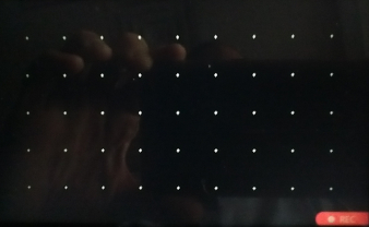
The REC button will be grayed out until an SD card is inserted. Once an SD card is inserted, the REC button text will become white and the button may then be used to start recording signal data to the SD card.
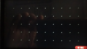
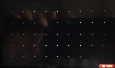
While it is recording, the REC button will change into a STOP button, as shown below. Press the STOP button to stop recording. A new file will be written each time recording is started and stopped. The previous file will not be overwritten.
The onboard GUI is available whether the Quanser Mechatronic Sensors Trainer is tethered to a PC or not. To access the onboard GUI, press and hold the joystick button while swiping down from the top, center of the touch screen. This will display the first of two Sensor pages from which a great deal of functionality is accessible. See the Quanser Mechatronic Sensors Trainer GUI help for details.
The Quanser Mechatronic Sensors Trainer I/O channels are described below.
Display
The LCD display on Quanser Mechatronic Sensors Trainer is a graphical color LCD display. Both text or graphics may be written to the display using the LCD Display block. To use the LCD Display block, set the LCD to and the URI to lcd://localhost:0. The display supports normal mode or dark mode, as well as an image or text. It can also rotate the display. To format text for the display, use the String Print block, which supports a superset of standard C format strings. The display currently supports the Basic Latin character set as well as the Latin-1 Supplement. For images, the resolution of the display is 800 x 480 pixels.
The LCD display is intended for use by the user as both a display and a touch panel. It is possible to write both text and graphics to the display from the host computer (e.g. a PC or Raspberry Pi), as well as read the touch panel display. The LCD display normally displays a touch panel type grid to make it easier to identify the coordinates of finger(s) when reading the touch panel. The touch panel supports up to ten fingers simultaneously, reporting data such as the number of fingers, an identifier for each finger, the row and column location of each finger, as well as the weight and area and an event code for each finger.
Up to a 30 Hz frame rate may be used to drive the display. In this case, use a Sample time parameter of
qc_get_step_size * ceil(1 / 30 / qc_get_step_size). Since the LCD display also has a touch panel, the LCD Display
block will have outputs for the touch panel. The touch panel may be used with a sample time of 120 Hz. In this case, set the
Output sample time parameter to qc_get_step_size * ceil(1 / 120 / qc_get_step_size).
Cameras
The Quanser Mechatronic Sensors Trainer provides a color camera (OV5640) with up to 2592x1944 pixel resolution. The available camera resolutions are listed below:
|
Resolution |
Description |
|---|---|
|
160x120 |
Smallest resolution, 0.02MP 4:3 aspect ratio. |
|
176x144 |
0.03MP 11:9 aspect ratio. |
|
320x240 |
0.08MP 4:3 aspect ratio. |
|
640x480 |
0.3MP 4:3 aspect ratio. |
|
720x480 |
0.3MP 3:2 aspect ratio. |
|
720x576 |
0.4MP 5:4 aspect ratio. |
|
1024x768 |
0.8MP 4:3 aspect ratio. |
|
1280x720 |
0.9MP 16:9 aspect ratio. |
|
1920x1080 |
2.1MP 16:9 aspect ratio. |
|
2592x1944 |
Maximum resolution of 5.0MP 4:3 aspect ratio. |
The camera is accessed through the Multimedia API blocks: see the Video Capture block.
Communications
The communications ports provided with the Quanser Mechatronic Sensors Trainer can be utilized through the QUARC Communications blockset and the Quanser Stream API (see QUARC Communications Protocols).
SPI
For SPI communications, a sample URI for communications would be:
spi-mech-sensors-trainer-usb://localhost:0?baud='1000000',polarity='off',phase='off',lsb='off',frame='0'
where the frame option selects the SPI SS line to frame the SPI bus transaction (0-3 for user GPIO 0-3 or 4 for SPI CS line).
| Because the external SPI bus is shared by other sensors internal to the board, a chip select must be used with external devices. However, the baud rate and other SPI settings may still be configured. |
| Note that if a user GPIO is used for a chip select then it will be programmed as a digital output when the stream is connected. Care must be taken not to change this direction through the HIL interface, as it also has access to the same user GPIO! |
I2C
For I2C communications, a sample URI for communications would be:
i2c-mech-sensors-trainer-usb://localhost:0?baud='400000',address=0x69
where the address option specifies the I2C slave address. The only valid port is port 0. The baud rate must be 400 kHz.
| Because the external I2C bus is shared by other sensors internal to the board, the following I2C slave addresses must not be used: 0x10, 0x23, 0x2A, 0x40, or 0x68. |
Serial
For serial communications, a sample URI for communications would be:
serial://localhost:7?baud='115200',word='8',parity='none',stop='1'
where the port indicates the COM port for Quanser Mechatronic Sensors Trainer. The COM port may be determined by looking for in Device Manager under "Ports (COM & LPT)" for a serial device called "USB Serial Device (COMnn)", where nn is the COM port number. It supports baud rates from 1832 baud up to 15 MBaud, as well as 1, 1.5 or 2 stop bits, parity of none, even, odd, mark or space, and word lengths of 6 (only with parity), 7 or 8. Not all combinations are valid on all platforms.
Audio
The Quanser Mechatronic Sensors Trainer provides one speaker and two microphones. The microphones are located at left and right sides of the
back panel near the bottom. They are marked MIC L and MIC R for easy identification. The microphones
are intended for applications such as user interaction or sound localization, such as detecting the direction from which
a voice is heard. The microphones are presented as a stereo microphone on the host. When sound recorded using the
microphone is streamed to a stereo headset on the host, the stereo effect is readily apparent. The microphones record
24-bit sound at 48 kHz.
The speaker is located in the middle of the back panel below the LCD. It plays sound at 96 kHz. Left and right channels are merged into one, as there is only one speaker. The speaker is intended for applications such as user interaction.
Clocks
There is currently one hardware clock that may be used as a timebase for tasks. Its mode and initial frequency are not configurable.
Analog Inputs
The Quanser Mechatronic Sensors Trainer driver provides up to 12 analog inputs. Hence, analog input channel numbers range from 0 to 11.
Analog input channels 0 and 1 represent the analog joystick axes. Channel 0 is the left/right axis and channel 1 is the up/down axis. The joystick readings have been scaled to a range of ±1 representing the full range of motion.
The next five channels represent the light-dependent resistor (2), force sensing resistor (3), passive infrared sensor (4), infrared distance sensor (5) and load cell (6) respectively. The outputs are the voltages reported by the sensors.
Channel 7 is the current measured on the user header for the +3.3V supply. The external encoder and force sensing resistors are also powered by this 3.3V supply so attaching an external encoder or force sensing resistor will show up in the current draw. The value reported is in Amperes.
The last four channels (8 to 11) are optional and are only valid when the corresponding user GPIO has been configured as a single-ended analog input via the dio0_mode, dio1_mode, dio2_mode or dio3_mode option. They are labelled "analog input #0" to "analog input #3" respectively to correspond to the user GPIO numbering, even though the channel numbers are 8 through 11 respectively. They are single-ended inputs with 0.0V to 3.3V range and 16-bit resolution.
| Do not exceed the 0.0V to 3.3V range of the analog inputs! Doing so risks damaging the device. |
The analog inputs are enumerated in the table below for convenience:
|
Channel |
Description |
Units |
|---|---|---|
|
0 |
Joystick left/right |
Fraction between -1 and 1. |
|
1 |
Joystick up/down |
Fraction between -1 and 1. |
|
2 |
Light-dependent resistor |
Volts (0 to 3.3V) |
|
3 |
Force sensing resistor |
Volts (0 to 3.3V) |
|
4 |
Passive infrared |
Volts (0 to 3.3V) |
|
5 |
Infrared distance |
Volts (0 to 5V) |
|
6 |
Load cell |
Volts (-3.3V to 3.3V) |
|
7 |
User current |
Amperes |
|
8 |
Analog input #0 |
Volts (0 to 3.3V) |
|
9 |
Analog input #1 |
Volts (0 to 3.3V) |
|
10 |
Analog input #2 |
Volts (0 to 3.3V) |
|
11 |
Analog input #3 |
Volts (0 to 3.3V) |
Analog Outputs
The Quanser Mechatronic Sensors Trainer card does not support analog outputs.
Digital Inputs
The Quanser Mechatronic Sensors Trainer provides four bidirectional digital I/O lines, as well as twelve additional digital inputs related to the other sensors and 15 inputs related to the Gamepad interface for a total of 31 channels. Hence digital input channel numbers range from 0 to 30. Digital lines 0-3 are available on the 20-pin user header. A digital I/O line cannot be used as an input and output at the same time, nor can a user GPIO pin be used as a digital line and an SPI chip select at the same time.
| All digital channels are 3.3V. |
The first four digital I/O lines may be individually programmed as inputs or
outputs on the Quanser Mechatronic Sensors Trainer. All of those four channels which will be used for digital inputs
should be configured on the HIL Initialize
block's Digital Inputs tab. Set the Digital input channels field to all
the digital I/O channels that will be used as digital inputs on the board for the current diagram. For example, enter
0:3 to designate channels 0 through 3 as digital inputs. Specify
[0, 2, 3] to indicate that channels 0, 2 and 3 are to be configured
as digital inputs.
| Do not set a pin used as an SPI chip select as a digital input. |
The joystick not only provides X, Y axes, but also acts as a push button when pressed down. The additional digital inputs represent Button 0 (channel 4) and Button 1 (5), the joystick push button (6), the knob encoder A (7) and B (8) signals, a power alert (9), thermocouple fault (10), thermocouple short-circuit to VCC fault (11), thermocouple short-circuit to ground fault (12), thermocouple not connected fault (13), SD card present (14), buttons on the Gamepad page and finally a radar configuration error flag (30). The thermocouple fault input will be true if any of the other thermocouple faults occur and is false otherwise. The radar configuration error input is asserted when the specific combination of radar parameters selected in the board-specific options is not supported.
The knob encoder A and B lines let the user see the actual encoder A and B lines from which the knob encoder counts are derived. Since the knob has a low resolution encoder and is turned by hand, it is a good candidate for learning about encoders and how they work. The signals may also be used to derive one's own 1X, 2X or 4X quadrature counts.
The digital inputs are listed in the table below for convenience:
|
Channel |
Description |
|---|---|
|
0..3 |
User GPIO 0 to 3 |
|
4 |
Button 0 |
|
5 |
Button 1 |
|
6 |
Joystick pushbutton |
|
7..8 |
Knob encoder A and B respectively |
|
9 |
Power alert |
|
10 |
Thermocouple fault |
|
11 |
Thermocouple short-circuit to VCC |
|
12 |
Thermocouple short-circuit to GND |
|
13 |
Thermocouple not connected (open circuit) |
|
14 |
SD card present |
|
15 |
Gamepad page point-of-view North button |
|
16 |
Gamepad page point-of-view South button |
|
17 |
Gamepad page point-of-view West button |
|
18 |
Gamepad page point-of-view East button |
|
19 |
Gamepad page START button |
|
20 |
Gamepad page BACK button |
|
21 |
Gamepad page LEFT button |
|
22 |
Gamepad page RIGHT button |
|
23 |
Gamepad page left bumper (LB) |
|
24 |
Gamepad page right bumper (RB) |
|
25 |
Gamepad page Xbox button |
|
26 |
Gamepad page A button |
|
27 |
Gamepad page B button |
|
28 |
Gamepad page X button |
|
29 |
Gamepad page Y button |
|
30 |
Radar configuration error |
Digital Outputs
The Quanser Mechatronic Sensors Trainer provides four bidirectional digital I/O lines, as well as 16 additional digital outputs related to the other sensors for a total of 20. Hence digital output channel numbers range from 0 to 19. Digital lines 0-3 are available on the 20-pin user header. A digital I/O line cannot be used as an input and output at the same time.
| All digital channels are 3.3V. |
The first four digital I/O lines may be individually programmed as inputs or
outputs on the Quanser Mechatronic Sensors Trainer. All of those four channels which will be used for digital outputs
should be configured on the HIL Initialize
block's Digital Outputs tab. Set the Digital output channels field to all
the digital I/O channels that will be used as digital outputs on the board for the current diagram. For example, enter
0:3 to designate channels 0 through 3 as digital outputs. Specify
[0, 2, 3] to indicate that channels 0, 2 and 3 are to be configured
as digital outputs.
| Do not write to a pin that is used as an SPI chip select. |
The additional digital outputs are used to override the gamepad buttons and point-of-view hats.
The Quanser Mechatronic Sensors Trainer shows up in Windows as an Xbox 360 game controller (one of the many devices as which it is recognized). Normally, the joystick, joystick button, Button 0 and Button 1 are used for the game controller inputs so that the Quanser Mechatronic Sensors Trainer acts like a game controller. However, all of the gamepad controls may be overridden through the HIL interface, so that the user has complete control over its behaviour. Thus, the gamepad interface is completely customizable and can even be algorithmically controlled. The digital output include signals for each of the gamepad digital controls.
The digital outputs are listed in the table below for convenience:
|
Channel |
Description |
|---|---|
|
0..3 |
User GPIO 0 to 3 |
|
4..7 |
Gamepad override for point-of-view north, south west and east respectively |
|
8 |
Gamepad start button override |
|
9 |
Gamepad back button override |
|
10 |
Gamepad left joystick button (L3) override |
|
11 |
Gamepad right joystick button (R3) override |
|
12 |
Gamepad left bumper (LB) override |
|
13 |
Gamepad right bumper (RB) override |
|
14 |
Gamepad Xbox button override |
|
15 |
Gamepad unused button override |
|
16..17 |
Gamepad A and B button overrides respectively |
|
18..19 |
Gamepad X and Y button overrides respectively |
Encoder Inputs
The Quanser Mechatronic Sensors Trainer supports two quadrature encoder inputs, the knob encoder and the external encoder. The knob encoder is channel 0 and the external encoder available on the user encoder pins is channel 1. The knob encoder has a 16-bit counter and the external encoder has a 32-bit counter.
In order to set the encoder counters to a particular count or to change the default
quadrature or filter frequency when the model is loaded, the encoder inputs must
be configured on the HIL Initialize
block's Encoder Inputs tab. Set the Encoder input channels
field to all the encoder channels that will be used on the board for the current diagram.
For example, enter 0:1 to indicate channels 0 and 1 are used as encoder inputs.
Specify [1] to indicate that channel 1 is used as an encoder input.
If the vectors specified in these fields are shorter than the channel vector, the value of the last element in the vector will be used for the rest of the channels. Hence, a scalar value will apply to all channels specified in the Encoder input channels field.
Both encoders support 1X, 2X or 4X quadrature. For the knob encoder, valid initial count values range from -32768 to +32767. For the external encoder, valid initial count values range from -2147483648 to +2147483647. If the vectors specified in these fields are shorter than the channel vector, the value of the last element in the vector will be used for the rest of the channels. Hence, a scalar value will apply to all channels specified in the Encoder input channels field.
The Quanser Mechatronic Sensors Trainer default sign convention in quadrature (1X, 2X or 4X) mode increments the encoder counter value when the B channel signal leads the A channel signal. Conversely, the encoder counter value is decreased when A leads B. This sign convention can be changed in the Board-Specific Options, with the enc_dir option, for the external encoder channel, and with the knob_dir for the knob encoder. See the Board-Specific Options section below for more details.
Valid filter frequencies range from 937500 Hz to 240 MHz. Set the value to 240e6 to have no filtering.
PWM Outputs
The Quanser Mechatronic Sensors Trainer provides two optional PWM output channels. Hence, PWM output channels range from 0 to 1.
The PWM channels may have different PWM frequencies and duty cycles. PWM output 0 is enabled by setting the dio2_mode
card-specific option to "2". In that case, digital IO #2 is no longer available and the user GPIO 2 pin is
used for PWM output 0. PWM output 1 is enabled by setting the dio3_mode
card-specific option to "2". In that case, digital IO #3 is no longer available and the user GPIO 3 pin is
used for PWM output 1.
In order to configure the PWM mode or frequency, or to set the value of the PWM outputs when the model is loaded or unloaded, the PWM
outputs must be configured on the HIL Initialize block's
PWM Outputs tab. Set the PWM output channels field to all the PWM output channels that will be used on the
board for the current diagram. For example, enter 0:1 to indicate channels 0 and 1. Specify 1 to indicate channel 1 alone.
The PWM outputs are generic PWM outputs that are capable of producing conventional PWM, as well as the standard analog ESC protocols, namely standard PWM (1000us to 2000us), Oneshot125 (125us to 250us), Oneshot42 (42us to 84us) and Multishot (5us to 25us).
The ESC Output block is recommended for constructing the input to the PWM output channel since it allows a 0% to 100% throttle value to be used, and it will output the appropriate pulse time (for PWM-based protocols). Note that when using the ESC Output block, the PWM mode should be PWM_TIME_MODE (4) for PWM-based protocols.
The PWM parameters for each of these ESC protocols are tabulated below:
|
Protocol |
PWM Frequency |
Pulse Time Range |
Duty Cycle Range |
|---|---|---|---|
|
Standard PWM |
50 Hz (20ms) |
0.001 to 0.002 seconds (1ms to 2ms) |
0.05 to 0.1 (5% to 10%) |
|
Oneshot125 |
2000 Hz (500us) |
125e-6 to 250e-6 seconds (125us to 250us) |
0.25 to 0.5 (25% to 50%) |
|
Oneshot42 |
5952 Hz (168us) |
42e-6 to 84e-6 seconds (42us to 84us) |
0.25 to 0.5 (25% to 50%) |
|
Multishot |
20000 Hz (50us) |
5e-6 to 25e-6 seconds (5us to 25us) |
0.1 to 0.5 (10% to 50%) |
The maximum output frequency of the PWM outputs is 120 MHz. The number of bits of resolution decreases with increasing PWM output frequency. The PWM timebase is 240 MHz.
Set the PWM output frequency (a.k.a., pulse rate) in the "Frequencies in Hz or duty cycle" field. The
PWM output mode is typically set to duty cycle mode (0) or time mode (4) when driving ESCs or R/C servos.
Set the Initial PWM outputs and Final PWM outputs fields to the desired
initial and final output values respectively. The interpretation of these output values depends on the PWM mode selected.
If the vectors specified in these fields are shorter than the channel vector, the value of the last element in the vector
will be used for the rest of the channels. Hence, a scalar value will apply to all channels specified in the PWM output channels field.
Likewise, for the PWM output mode for example, the default value is [0 0] so that the first '0' applies
to the motor PWM, which must be duty cycle mode (0), and the second '0' applies to the rest of the PWM channels.
Other Inputs
The specific Other Input channels of the Quanser Mechatronic Sensors Trainer are described in the table below. SI units are used. There are 56063 input channels in total.
|
Other Input Channel |
Measurement Description |
Units |
|---|---|---|
|
0..63 |
Time of flight distance from each of the 64 zones |
(m) |
|
64..127 |
Time of flight standard deviation (sigma) for each of the 64 zones |
(m) |
|
128 |
Radar start of range (provided for convenience) |
(m) |
|
129 |
Radar length of range (provided for convenience). End of range is start + length. |
(m) |
|
130 |
Ultrasonic start of range (provided for convenience) |
(m) |
|
131 |
Ultrasonic length of range (provided for convenience). End of range is start + length. |
(m) |
|
132 |
Ultrasonic distance measurement. |
(m) |
|
3000, 3001, 3002 |
Angular velocity around the X, Y, and Z-axis, respectively (from gyroscope) |
(rad/s) |
|
4000, 4001, 4002 |
Linear acceleration along the X, Y, and Z-axis, respectively (from accelerometer) |
(m/s2) |
|
8000, 8001, 8002 |
Magnetic Field Along The X, Y, and Z-axis |
(T) |
|
9000 |
Pressure from weather sensor. |
(Pa) |
|
10000 |
Temperature of weather sensor. |
(°C) |
|
10001 |
Thermocouple temperature. |
(°C) |
|
10002 |
Thermocouple internal temperature (for comparison). |
(°C) |
|
10003 |
Temperature of IMU sensor. |
(°C) |
|
10004 |
Temperature of CPU. |
(°C) |
|
11000 |
Humidity from weather sensor. |
(%) |
|
11001 |
Color clear (ambient) from color sensor. |
(%) |
|
11002 |
Color red from color sensor. |
(%) |
|
11003 |
Color green from color sensor. |
(%) |
|
11004 |
Color blue from color sensor. |
(%) |
|
11005 |
Color infrared from color sensor. |
(%) |
|
11006..11069 |
Time of flight reflectance for each of the 64 zones. |
(%) |
|
11070 |
Gamepad page left joystick (left/right). |
(±%) |
|
11071 |
Gamepad page left joystick (up/down). |
(±%) |
|
11072 |
Gamepad page right joystick (left/right). |
(±%) |
|
11073 |
Gamepad page right joystick (up/down). |
(±%) |
|
11074 |
Gamepad page left trigger. |
(%) |
|
11075 |
Gamepad page right trigger. |
(%) |
|
12000 |
The period of the PWM input capture measurement. |
(s) |
|
12001 |
The pulse width of the PWM input capture measurement. Whether it is the high or low pulse width depends on the enc_dir option. |
(s) |
|
13000..13063 |
Time of flight number of targets detected for each of the 64 zones. |
(count) |
|
13064 |
Number of valid radar points in the radar distance and amplitude data (twice this number for IQ amplitudes). |
(count) |
|
13065 |
Number of valid ultrasonic points in the ultrasonic distance and amplitude data (twice this number for IQ amplitudes). |
(count) |
|
16000 |
Radar service (provided for convenience). |
(enumeration) |
|
10000000..10025644 |
Radar distance for each sample point in a scan (pair with amplitude data). |
(m) |
|
10050000..10050449 |
Ultrasonic distance for each sample point in a scan (pair with amplitude data). |
(m) |
|
21000000..21028769 |
Radar amplitudes for each sample point in a scan (pair with distance data). For IQ data, the in-phase (I) and quadrature-phase (Q) amplitudes are interleaved (I0,Q0,I1,Q1,...) so there are twice as many amplitude values as distance values. |
(m) |
|
21050000..21050899 |
Ultrasonic amplitudes for each sample point in a scan (pair with distance data). For IQ data, the in-phase (I) and quadrature-phase (Q) amplitudes are interleaved (I0,Q0,I1,Q1,...) so there are twice as many amplitude values as distance values. |
(m) |
Channel numbers for Other Input or Output channels use predefined ranges for each type of measurement to ensure consistency between data acquisition devices. Refer to QUARC Other Channels for a list of the Other Input or Output channel number ranges defined for any HIL Data Acquisition Card and their SI units.
Other Outputs
The specific Other Output channels of the Quanser Mechatronic Sensors Trainer are described in the table below. SI units are used.
|
Other Output Channel |
Measurement Description |
Units |
|---|---|---|
|
11000..11002 |
LED0 color as red, green and blue percentages respectively |
(%) |
|
11003..11005 |
LED1 color as red, green and blue percentages respectively |
(%) |
|
11006 |
Dual infrared LED percentage |
(%) |
|
11007 |
Gamepad override for left joystick left/right |
(±%) |
|
11008 |
Gamepad override for left joystick up/down |
(±%) |
|
11009 |
Gamepad override for right joystick left/right |
(±%) |
|
11010 |
Gamepad override for right joystick up/down |
(±%) |
|
11011 |
Gamepad override for left trigger |
(±%) |
|
11012 |
Gamepad override for right trigger |
(±%) |
Channel numbers for Other Input or Output channels use predefined ranges for each type of measurement to ensure consistency between data acquisition devices. Refer to QUARC Other Channels for a list of the Other Input or Output channel number ranges defined for any HIL Data Acquisition Card and their SI units.
Interrupts
The Quanser Mechatronic Sensors Trainer card, or its driver, does not support any interrupt sources.
Watchdog
The Quanser Mechatronic Sensors Trainer card does not support a watchdog timer.
Board-Specific Options
The Quanser Mechatronic Sensors Trainer has a number of board-specific options to control specialized functionality of the Quanser Mechatronic Sensors Trainer. These options configure many of the sensors.
accel_avg
This option sets the number of samples averaged by the accelerometer. Valid values are 1, 4, 8, 16 or 32. Any values between 1 to 32 will be coerced to the closest power of two below the given value.
accel_filter
This option sets the 3dB filter bandwidth of the low-pass filter used by the accelerometer. Note that filtering is disabled if the accel_rate option is greater than 1125 Hz. The value is in units of Hertz. Valid values are 5.7, 11.5, 23.9, 50.4, 111.4, 246 or 473 Hz. Any values between 5.7 and 473 will be coerced to the closest valid frequency.
accel_fs
This option sets the accelerometer full-scale range. Valid values are 2, 4, 8 or 16. The units are g's. The default is 16 g.
accel_rate
This option sets the output data rate of the accelerometer. Valid values are 4500 or 1125 / n, where n = 1..4096. For example, 1125, 562.5, 375, etc. The units are Hertz. Values within the range will be coerced to the nearest valid value. Note that if a value greater than 1125 is entered then low-pass filtering will be disabled to achieve the desired rate.
adc1_os
This option sets the oversampling factor for ADC1, which reads the joystick axes. The name "adc1_oversampling" may also be used. Valid values are 2^n where n=5-10, i.e., 32, 64, 128, 256, 512 or 1024. Values within the range will be coerced to the nearest valid value. Smaller values result in faster conversion times but more noise. Larger values result in slower conversion times but cleaner signals. A value of 1024 yields a conversion rate of 377 Hz. The default oversampling factor is 64.
adc2_os
This option sets the oversampling factor for ADC2, which reads the force sensing resistor and light-dependent resistor. The name "adc2_oversampling" may also be used. Valid values are 2^n where n=5-10, i.e., 32, 64, 128, 256, 512 or 1024. Values within the range will be coerced to the nearest valid value. Smaller values result in faster conversion times but more noise. Larger values result in slower conversion times but cleaner signals. The minimum value is designed for an 8 kHz conversion rate. A value of 1024 yields a conversion rate of 377 Hz. The default oversampling factor is 64.
adc3_os
This option sets the oversampling factor for ADC3, which reads the passive infrared sensor, infrared distance sensor, CPU temperature, and analog inputs 0-3 (when the digital I/O are configured as analog inputs). The name "adc3_oversampling" may also be used. Valid values are 2^n where n=3-10, i.e., 8, 16, 32, 64, 128, 256, 512 or 1024. Values within the range will be coerced to the nearest valid value. Smaller values result in faster conversion times but more noise. Larger values result in slower conversion times but cleaner signals. A value of 1024 yields a conversion rate of 108 Hz. The default oversampling factor is 16.
btn0_pol
This option sets the polarity of the left pushbutton (Button 0). Valid values "0", "no" or "false" and "1", "yes" or "true". The name "button0_polarity" may also be used. If it is 1 then the button is active-high (producing a 1 when pressed) while if it is 0 then the button is active-low (producing a 0 when pressed).
btn1_pol
This option sets the polarity of the right pushbutton (Button 1). Valid values "0", "no" or "false" and "1", "yes" or "true". The name "button1_polarity" may also be used. If it is 1 then the button is active-high (producing a 1 when pressed) while if it is 0 then the button is active-low (producing a 0 when pressed).
color_ag
This option sets the color sensor analog gain. Valid values are 0.5, 1.0, 2.0 or 4.0.
color_dg
This option sets the color sensor digital gain. Valid values are 1, 2 or 4.
color_int
This option sets the color sensor integration time. Valid values are 50, 100, 200, or 400. The units are milliseconds.
dio0_mode
This option sets the alternate functionality of user GPIO 0 on the 20-pin header. Valid values are currently:
|
Value |
Description |
|---|---|
|
"0" or "dig" or "digital" or "gpio" |
The default GPIO mode where the pin functions as a digital I/O pin. |
|
"1" or "ana" or "analog" |
The user GPIO 0 pin is reconfigured as analog input channel 8 (labelled "analog input #0"). |
dio1_mode
This option sets the alternate functionality of user GPIO 1 on the 20-pin header. Valid values are currently:
|
Value |
Description |
|---|---|
|
"0" or "dig" or "digital" or "gpio" |
The default GPIO mode where the pin functions as a digital I/O pin. |
|
"1" or "ana" or "analog" |
The user GPIO 1 pin is reconfigured as analog input 9 (labelled "analog input #1"). |
dio2_mode
This option sets the alternate functionality of user GPIO 2 on the 20-pin header. Valid values are currently:
|
Value |
Description |
|---|---|
|
"0" or "dig" or "digital" or "gpio" |
The default GPIO mode where the pin functions as a digital I/O pin. |
|
"1" or "ana" or "analog" |
The user GPIO 2 pin is reconfigured as analog input 10 (labelled "analog input #2"). |
|
"2" or "pwm" |
The user GPIO 2 pin is reconfigured as PWM output #0. |
dio3_mode
This option sets the alternate functionality of user GPIO 3 on the 20-pin header. Valid values are currently:
|
Value |
Description |
|---|---|
|
"0" or "dig" or "digital" or "gpio" |
The default GPIO mode where the pin functions as a digital I/O pin. |
|
"1" or "ana" or "analog" |
The user GPIO 3 pin is reconfigured as analog input 11 (labelled "analog input #3"). |
|
"2" or "pwm" |
The user GPIO 3 pin is reconfigured as PWM output #1. |
enc_dir
This option changes the direction of the external encoder. The default value is zero. Setting it to 1 will cause the encoder to count in the opposite direction. In PWM input capture mode, setting this option to zero causes it to measure the pulse width of the high pulse. Setting it to 1 causes it to measure the pulse width of the low pulse.
enc_mode
This option sets the alternate functionality of the external encoder 5-pin header. Valid values are currently:
|
Value |
Description |
|---|---|
|
"0" or "enc" or "encoder" |
The default encoder mode where the pins are used with an external encoder. |
|
"1" or "pwm" |
The external encoder ENC A pin (pin 5) is reconfigured as a PWM input capture pin measuring period and pulse width (see other inputs 12000 and 12001). |
enc_freq
This options sets the frequency of the timebase used for the external encoder. It is particularly useful for filtering or controlling the range of frequencies detectable by the PWM input capture mode. The minimum value of this parameter is 3662.109375 Hz, and the maximum value is 240e6 Hz (240 MHz). The range of pulse widths or periods that may be detected in PWM input capture mode will range from 1.0 / enc_freq seconds to 65535 / enc_freq seconds. Be aware that the actual frequency will be 240e6 / N, where N is an integer so specifying a frequency of 200e6 will actually result in an encoder frequency of 120e6 Hz (120 MHz). Better accuracy is achieved when the frequency detected is closer to enc_freq / 65535 (the low end of the range) because then there are more timer ticks. The default value for this option is 240e6 (240 MHz).
gyro_avg
This option sets the number of samples averaged by the gyroscope. Valid values are 1, 2, 4, 8, 16, 32, 64 or 128. Any values between 1 to 128 will be coerced to the closest power of two below the given value.
gyro_filter
This option sets the 3dB filter bandwidth of the low-pass filter used by the gyroscope. Note that filtering is disabled if the gyro_rate option is greater than 1125 Hz. The value is in units of Hertz. Valid values are 5.7, 11.6, 23.9, 51.2, 119.5, 151.8, 196.6 and 361.4 Hz. Any values between 5.7 and 361.4 will be coerced to the closest valid frequency.
gyro_fs
This option sets the gyroscope full-scale range. Valid values are 250, 500, 1000 and 2000. The units are degrees per second. The default is 2000 degress per second.
gyro_rate
This option sets the output data rate of the gyroscope. Valid values are 9000 or 1125 / n, where n = 1..256. For example, 1125, 562.5, 375, etc. The units are Hertz. Values within the range will be coerced to the nearest valid value. Note that if a value greater than 1125 is entered then low-pass filtering will be disabled to achieve the desired rate.
hum_over
This option sets the oversampling ratio used for the weather sensor's humidity measurement. Valid values range from 0, 1, 2, 4, 8 or 16. The name "humidity_oversampling" may also be used. A value of 0 causes the sensor to be skipped entirely.
knob_dir
This option changes the direction of the knob encoder. The default value is zero. Setting it to 1 will cause the encoder to count in the opposite direction.
load_gain
This option changes the gain of the load cell. Valid values are 1, 2, 4, 8, 16, 32, 64 or 128. The default value is 128. The name "load_cell_gain" may also be used.
load_rate
This option changes the sampling rate of the load cell in Hertz. Valid values are 10, 20, 40, 80 or 320. The default value is 320. The name "load_cell_rate" may also be used.
press_over
This option sets the oversampling ratio used for the weather sensor's pressure measurement. Valid values range from 0, 1, 2, 4, 8 or 16. The name "pressure_oversampling" may also be used. A value of 0 causes the sensor to be skipped entirely.
radar_bins
This option sets the number of power bins for the radar. Valid values are 0 to 437. The name "radar_power_bins" may also be used. The number of power bins should not exceed the radar_len / 0.016. Set this parameter to zero to use the maximum number of power bins for the given radar length (the default).
radar_down
This option sets the radar downsampling factor. Valid values are 1, 2, 4 or 8. The name "radar_downsampling" may also be used. The downsampling factor is used to decimate the samples collected. With a downsampling factor of 1, the envelope and IQ services have a base step length of approximately 0.5 mm. With a downsampling factor of 4, it has a base step size of about 2 mm. This reduces the resolution but also requires less processing since there are fewer data points. For the sparse service, a downsampling factor of 1 has a base step length of approximately 6 cm. For the sparse service, setting the downsampling factor too high can lead to gaps in the data so that small objects "disappear" between sampling points.
radar_gain
This option sets the radar receiver gain. Valid values range from 0.0 to 1.0. The name "radar_receiver_gain" may also be used. The receiver gain should be reduced if the measurement is saturating.
radar_hwaas
This option sets the radar's hardware-accelerated average samples. Valid values range from 1 to 63. This parameter controls the number of samples that are collected and averaged to compute one point in the measurement data. The higher the number of samples that are averaged, the better the signal-to-noise ratio (SNR) of the measurement. A reasonable value for the IQ service is 10.
radar_len
This option sets the length of the radar's range. Valid values range from 0.18 to 7.0. The units are meters. The name "radar_length" may also be used. The radar will scan from radar_start to radar_start + radar_len.
radar_mur
This option sets the maximum usable range (MUR) of the radar. Valid values are 6 or 9. The units are meters. It is recommended that this parameter be left at 6 (the default value). The maximum usable range is the maximum distance at which an object may be located before its reflected pulse takes so long to return that it becomes part of the next measurement and looks like a much shorter distance. The higher setting thus increases the measurement time required for a sweep.
radar_noise
This option is a boolean option indicating whether noise level normalization should be performed. The name "radar_noise_normalization" may also be used. Noise level normalization involves normalizing the data to the noise floor of the measurement. Normalization is available for the power bins, envelope and IQ services but not the sparse service. Normalization results in more constant signals for different temperatures and sensors. When normalization is active, the sensor receiver gain and hardware-accelerated average samples parameters will have less effect.
radar_prof
This option sets the radar profile. Valid values range from 1 to 5. The name "radar_profile" may also be used. The different profiles optimize the pulse length based on depth resolution or radar loop gain. Profile 1 uses the shortest pulse and is designed for applications that are detecting multiple objects or short distances (less than 20 cm). The higher the profile number, the longer the pulse. Longer pulses are more suitable for applications dealing with objects that have weak reflections or that are more distant from the sensor. Profiles 2 and 3 are recommended for intermediate distances of 20 cm to 1 m. Profiles 4 and 5 maximize the radar loop gain, which allows longer distances to be detected but results in lower precision in the distance estimate. Profiles 4 and 5 are used with the Sparse service and operate over distances larger than 1 m. Starting with profile 2 or 3 is recommended and are the preferred profiles when using the IQ service.
radar_run
This option sets the radar envelope running average factor. Valid values range from 0.0 to 1.0. The name "radar_running_average" may also be used. The radar envelope running average factor is used to compute a running average of multiple envelopes over time to filter out noise. The average is computed using an exponential window function. A value of 0.0 turns off time filtering of sweeps. The default value is 0.7.
radar_samp
This option sets the radar sampling mode. Valid values "0", "no", "false" or "A" and "1", "yes", "true" or "B". The name "radar_sampling_mode" may also be used. The sampling mode affects how the data is sampled in the sensor. Mode A is optimized for maximizing the independence in the depth points and therefore yields a higher depth resolution than mode B. It is more suitable for gesture recognition and measuring moving objects. Mode B maximizes the signal-to-noise ratio (SNR) per unit time. It is more suitable for measuring small movements detected over long ranges. It has an SNR approximately 3dB better than mode A. Sampling mode A is typically used, but when using the IQ service with profile 1 then sampling mode B and a hardware-accelerated average samples value of at least 20 is recommended (see IQ Service).
radar_serv
This option sets the radar service. Valid values are enumerated in the table below. The name "radar_service may also be used.
|
Service |
Option Value |
Description |
|---|---|---|
|
None |
"0" or "none" |
Radar is disabled to conserve power. |
|
Distance |
"1", "dist" or "distance" |
The radar distance service measures the distance of objects from the sensor and provides their distance and the associated amplitude of the measurement. |
|
Presence |
"2", "pres" or "presence" |
The radar presence service simply detects whether an object is present and returns the distance to the object and a confidence score. |
|
Power Bins |
"3", "pwr" or "power" |
The radar power bins service measures the received energy at different distances from the sensor. It transmits a sequence of radar pulses and measures the energy content of the returning echoes for a various time delays from when the pulses were transmitted. The longer the time delay, the further the distance. It is a coarser version of the Envelope service and is suitable for applications where large objects are measured at short distances, such as parking. It provides distance versus amplitude samples for each measurment. |
|
Envelope |
"4", "env" or "envelope" |
The radar envelope service also measures the received energy at different distances from the sensor. It transmits a sequence of radar pulses and measures the energy content of the returning echoes for a various time delays from when the pulses were transmitted. The longer the time delay, the further the distance. It is has finer resolution than the Power Bins service and may be tuned for different ranges. It provides distance versus amplitude samples for each measurment. |
|
IQ |
"5" or "iq" |
The radar IQ service measures both in-phase (I) and quadrature (Q) components of the returning energy content from a sequence of radar pulses. It provides the most complete information from the esnsor. It provides both in-phase and quadrature amplitudes for each measurement. The IQ data is interleaved in the amplitude data so there are twice as many amplitude points as distances. The IQ data may be used to detect subtle motion in the scene, such as breathing rate. |
|
Sparse |
"6", "spar" or "sparse" |
The radar sparse service measures returning energy in approximately 6 cm intervals. Since the reflections are highly undersampled, it is not designed for the detection of static objects but instead for the detection of moving objects, particularly since it produces repeated scans of the entire range in a single measurement. Plotting the changes in a particular element of the measurements over time will reconstruct the motion of the object as it approaches or recedes from the sensor. See Sparse Service. |
radar_start
This option sets the start of the radar's range. Valid values range from 0.0 to 7.0. The units are meters. The radar will scan from radar_start to radar_start + radar_len.
radar_sweeps
This option sets the number of sweeps per frame. Valid values range from 1 to 64. The name "radar_sweeps_per_frame" may also be used. This parameter is used with the Presence and Sparse services to set the number of sweeps per frame.
radar_swprate
This option sets the sweep rate for each sweep in a frame. Valid values range from 0.0 to 3000.0. A value of 0.0 means as fast as possible. The units are Hertz. The name "radar_sweep_rate" may also be used. This parameter is used with the Sparse service to set the sweep rate for sweeps in a frame.
temp_over
This option sets the oversampling ratio used for the weather sensor's temperature measurement. Valid values range from 0, 1, 2, 4, 8 or 16. The name "temperature_oversampling" may also be used. A value of 0 causes the sensor to be skipped entirely.
tof_freq
This option sets the time of flight sensor ranging frequency. Valid values range from 1 to 60. The units are Hertz. Note that the 8x8 resolution only supports ranging frequencies from 1 to 15 Hz. The 4x4 resolution supports the full 1 to 60 Hz range.
tof_int
This option sets the time of flight sensor integration time. Valid values range from 2 to 1000. The units are milliseconds. Note that the integration time and ranging frequency are interrelated so not all combinations are valid.
tof_order
This option sets the time of flight sensor target order. Valid values are "0", "no", "false" or "close" to use the closest target, and "1", "yes", "true" or "strong" to use the strongest target.
tof_res
This option sets the time of flight sensor resolution. Valid values are "0", "no", "false" or "4x4" for 4x4 resolution and "1", "yes", "true" or "8x8" for 8x8 resolution. The name tof_resolution may also be used.
tof_sharp
This option sets the time of flight sensor sharpener. Valid values range from 0 to 99, representing a percentage.
ultra_int
This option sets the interval used for sampling by the ultrasonic sensor. Valid values range from 50 to 1000. The units are milliseconds. The name ultrasonic_interval may also be used.
ultra_len
This option sets the length used for the ultrasonic sensor range. Valid values range from 0.0 to 5.0. The units are meters. The name ultrasonic_length may also be used. The range goes from ultra_start to ultra_start + ultra_length.
ultra_serv
This option sets the current ultrasonic service. Valid values are shown in the table below. The name ultrasonic_service may also be used.
|
Service |
Option Value |
Description |
|---|---|---|
|
None |
"0" or "none" |
Ultrasound is disabled to conserve power. |
|
Distance |
"1", "dist" or "distance" |
The ultrasonic distance service measures the distance of an object from the sensor and provides its distance. |
|
IQ |
"2" or "iq" |
The ultrasonic IQ service measures both in-phase (I) and quadrature (Q) components of the returning energy content from a sequence of ultrasonic pulses. It provides the most cmoplete information from the esnsor. It provides both in-phase and quadrature amplitudes for each measurement. The IQ data is interleaved in the amplitude data so there are twice as many amplitude points as distances. The IQ data may be used to detect subtle motion in the scene. |
ultra_start
This option sets the start of the ultrasonic sensor range. Valid values range from 0.0 to 5.0. The units are meters. The name ultrasonic_start may also be used. The range goes from ultra_start to ultra_start + ultra_length.
weather_filt
This option sets the IIR filter coefficent for the weather sensor. Valid values are 0, 2, 4, 8 or 16. The name "weather_filter" may also be used. A value of 0 turns filtering off.
weather_standby
This option sets the inactive duration (also known as standby duration) for the weather sensor. Valid values range from 0.5 to 1000.0. The units are milliseconds. The closest valid duration to the one specified will be used.
Properties
The Quanser Mechatronic Sensors Trainer supports the following integer properties:
|
Property Name |
Property Code |
Description |
|---|---|---|
|
PROPERTY_INTEGER_VENDOR_ID |
0 |
The USB vendor identifier of the device. |
|
PROPERTY_INTEGER_PRODUCT_ID |
1 |
The USB product identifier of the device. |
|
PROPERTY_INTEGER_FIRMWARE_MAJOR_VERSION |
10 |
The major version of the firmware. |
|
PROPERTY_INTEGER_FIRMWARE_MINOR_VERSION |
11 |
The minor version of the firmware. |
|
PROPERTY_INTEGER_FIRMWARE_BUILD |
12 |
The PCB revision. |
|
PROPERTY_INTEGER_NUMBER_OF_ANALOG_INPUTS |
16 |
The number of analog input channels. |
|
PROPERTY_INTEGER_NUMBER_OF_ENCODER_INPUTS |
17 |
The number of encoder input channels. |
|
PROPERTY_INTEGER_NUMBER_OF_DIGITAL_INPUTS |
18 |
The number of potential digital input channels. |
|
PROPERTY_INTEGER_NUMBER_OF_OTHER_INPUTS |
19 |
The number of other input channels. |
|
PROPERTY_INTEGER_NUMBER_OF_ANALOG_OUTPUTS |
20 |
The number of analog output channels. |
|
PROPERTY_INTEGER_NUMBER_OF_PWM_OUTPUTS |
21 |
The number of PWM output channels. |
|
PROPERTY_INTEGER_NUMBER_OF_DIGITAL_OUTPUTS |
22 |
The number of potential digital output channels. |
|
PROPERTY_INTEGER_NUMBER_OF_OTHER_OUTPUTS |
23 |
The number of other output channels. |
|
PROPERTY_INTEGER_NUMBER_OF_CLOCKS |
24 |
The number of clocks. |
|
PROPERTY_INTEGER_NUMBER_OF_INTERRUPTS |
25 |
The number of interrupt channels. |
|
PROPERTY_INTEGER_IS_SIMULATION |
26 |
Whether the device is a simulated device (1) or actual device (0). |
Connectors
The Quanser Mechatronic Sensors Trainer has a number of connectors for sensors or expansion I/O. These connectors and their pinouts are listed below.
| Note that all pins are 3.3V and are not 5V tolerant unless marked otherwise. The analog inputs only support 0 to +3.3V. Exceeding these voltages may damage the board! |
User I/O Connector
3.3V ― | 20 | 19 | ― Ground |
DIO0 / ADC0 ↔ | 18 | 17 | ― Ground |
DIO1 / ADC1 ↔ | 16 | 15 | ― Ground |
DIO2 / ADC2 / PWM0 ↔ | 14 | 13 | ― Ground |
DIO3 / ADC3 / PWM1 ↔ | 12 | 11 | ― Ground |
SPI CIPO → | 10 | 9 | → SPI CLK |
SPI COPI ← | 8 | 7 | → SPI CS |
I2C SDA ↔ | 6 | 5 | ↔ I2C SCL |
UART TX ← | 4 | 3 | ← UART RX |
FSR IN1 → | 2 | 1 | → FSR OUT1 |
1 Dedicated Force Sensing Resistor (FSR) pins
Load Cell Connector
3.3V 2 ― | 4 | |
Ground ― | 3 | |
VIN+ → | 2 | |
VIN- → | 1 |
2 Dedicated Load Cell power supply. Do not use for anything else.
Encoder Connector
ENC B3 → | 5 | |
5V ― | 4 | |
ENC A / CAP3 → | 3 | |
NC ― | 2 | |
Ground ― | 1 |
3 5V tolerant input pins
Thermocouple Connector
VIN+ → | 2 |
VIN- → | 1 |
Legend
→▯← | = | input |
←▯→ | = | output |
↔▯↔ | = | bidirectional I/O |
= | 3.3V signal | |
= | power | |
= | ground |
Targets
|
Target |
Supported |
Comments |
|---|---|---|
|
No |
Not supported. |
|
|
Yes |
Fully supported. |
|
|
No |
Not supported. |
|
|
No |
Not supported. |
|
|
No |
Not supported. |
|
|
No |
Not supported. |
|
|
No |
Not supported. |
|
|
No |
Not supported. |
|
|
Yes |
Fully supported. |
|
|
No |
Not supported. |
|
|
No |
Not supported. |
|
|
No |
Not supported. |
|
|
No |
Not supported. |
|
|
No |
Not supported. |
|
|
No |
Last fully supported in QUARC 2018. |
|
|
Rapid Simulation (RSIM) Target |
Yes |
Supported with no communication to the hardware. |
|
Normal simulation |
Yes |
Supported with no communication to the hardware. |
Copyright ©2026 Quanser Inc. This page was generated 2026-05-13. Submit feedback to Quanser about this page.
Link to this page.
