
LCD Display
Prints to an LCD display.
Library
QUARC Targets/Devices/Third-Party/Displays MATLAB Command Line Click to copy the following command line to the clipboard. Then paste it in the MATLAB Command Window: qc_open_library('quarc_library/Devices/Third-Party/Displays')
Description
The LCD Display block prints a string or an image to an LCD display. The LCD display is typically driven by an I2C or SPI line and so the block takes a URI as an argument to identify the communications protocol with which to communicate with the display. Universal Resource Identifiers (URI), such as i2c-cpu://localhost:8?address=0x3E,baud=400000, are used by QUARC for all its communications because it provides a uniform, extensible and flexible means of identifying the communication protocol to use and the associated communication parameters. Refer to Universal Resource Identifiers for more information.
The LCD Display block supports two display modes: text and image. All LCD displays support text mode. Image mode is only supported by graphical LCD displays, like the Sharp LS012B7DD01, LS027B7DH01 and by the Surenoo WS0010, which has a graphics mode.
In text mode, the LCD Display block takes a fixed or variable-size input string to print to the display. Use the QUARC String blocks, such as the String Constant block or String Print block to generate the string. QUARC strings are fixed or variable-sized uint8 signals that represent UTF-8 unicode strings. Refer to Variable-Size Signals for more information on variable-size signals.
The block also takes a line and column input for specifying the line and column of the display at which to start printing the text. Line 0 is the first line and column 0 is the first column. Hence, leaving these inputs unconnected will cause the text to appear in the top, left corner of the display.
To clear the display, add a formfeed character, '\f', to the string being displayed. For example, to clear the display before printing "Hello world!", pass the string "\fHello world!" to the block.
Newlines will result in the text going to the next line. Hence, the string "Hello\nworld will print "Hello" on the starting line and "world" on the next line.
In image mode, the LCD Display block takes an image as an input to draw on the display. The image format is greyscale HxW. Black and white LCDs will treat values from 0..127 as one colour and 128..255 as the other colour. The input is typically a static image or an image produced using an Image Compare block.
The LCD Display block also allows the display to be rotated if the LCD display is graphical, like the Sharp LS012B7DD01 or LS027B7DH01.
For touch screens, the block provides additional outputs related to touch information. These outputs have a separate sample rate, specified via the Output sample time parameter, so that touch data may be sampled at a faster rate than the LCD display frame rate.
Helpful Hints
Black and White Displays
 To optimally display grayscale images, like camera feeds, on graphical black-and-white displays, like the LCD display of
the Quanser QCar 2, use the Image Transform block with the
Dither (1-bit) algorithm to transform grayscale images into black-and-white for display.
To optimally display grayscale images, like camera feeds, on graphical black-and-white displays, like the LCD display of
the Quanser QCar 2, use the Image Transform block with the
Dither (1-bit) algorithm to transform grayscale images into black-and-white for display.
Input Ports
str
A fixed or variable-sized uint8 signal containing the text to print to the LCD display. This port is only visible in text display mode.
img
A fixed or variable-sized uint8 signal containing the image to draw on the LCD display. For color displays, it may be two-dimensional (HxW) for grayscale images or three-dimensional (HxWx3) for color images. For grayscale or black and white display, it must be two-dimensional. An image of any size may be used but it will be cropped to fit on the display.
The Sharp LS012B7DD01 display has a 38x184 pixel (HxW) resolution. The Sharp LS027B7DH01 display has a 240x400 pixel (HxW) resolution. The Quanser Mechatronic Sensors Trainer display is a color display with 800x480 (HxWx3) resolution.
This port is only visible in image display mode.
line
The line number at which to start printing the text, or the pixel row number at which to start drawing the image. Line 0 is the first line at the top of the display and pixel row 0 is the first row. In text mode, the line number is the character line, but in image mode it is the pixel row coordinate.
col
The column number at which to start printing the text, or the pixel column number at which to start drawing the image. Column 0 is the first column at the left edge of the display and pixel column 0 is the first column. In text mode, the column number is the character number, but in image mode it is the pixel column coordinate.
clr
A 3-vector containing the red, green and blue colour values for text (in that order). This input is only present for RGB displays such as the Quanser Mechatronics Sensors Trainer USB LCD display when text mode is being used. The Color Constant block may be used to provide this input if a constant color is required.
Output Ports
err
Indicates whether an error occurred while printing to the LCD display. If an error occurred, it will be a negative QUARC error code. Otherwise zero will be output.
gesture
The touch gesture that was performed. Not all touch displays provide a value for this output. Valid values are listed in the table below:
|
Name |
Value |
Description |
|---|---|---|
|
TOUCH_GESTURE_NONE |
0 |
No gesture has been performed. |
|
TOUCH_GESTURE_SINGLE_PAN_NORTH |
16 |
Single finger pan towards the north. |
|
TOUCH_GESTURE_SINGLE_PAN_EAST |
20 |
Single finger pan towards the east. |
|
TOUCH_GESTURE_SINGLE_PAN_SOUTH |
24 |
Single finger pan towards the south. |
|
TOUCH_GESTURE_SINGLE_PAN_WEST |
28 |
Single finger pan towards the west. |
|
TOUCH_GESTURE_SINGLE_CLICK |
32 |
Single finger tap. |
|
TOUCH_GESTURE_DOUBLE_CLICK |
34 |
Single finger double tap. |
|
TOUCH_GESTURE_SINGLE_ROTATE_RIGHT |
40 |
Single finger rotate right. |
|
TOUCH_GESTURE_SINGLE_ROTATE_LEFT |
41 |
Single finger rotate left. |
|
TOUCH_GESTURE_ZOOM_IN |
72 |
Zoom in. |
|
TOUCH_GESTURE_ZOOM_OUT |
73 |
Zoom in. |
|
TOUCH_GESTURE_DOUBLE_ROTATE_LEFT |
129 |
Double finger rotate left. |
|
TOUCH_GESTURE_DOUBLE_ROTATE_RIGHT |
130 |
Double finger rotate right. |
rows
A vector containing the row coordinates of all the current touch points. The number of valid elements is indicated by the # output.
cols
A vector containing the column coordinates of all the current touch points. The number of valid elements is indicated by the # output.
ids
A vector containing the identifiers associated with all the current touch points. The number of valid elements is indicated by the # output.
events
A vector containing the event codes associated with all the current touch points. The number of valid elements is indicated by the # output. Not all touch displays provide a value for this output. Valid event codes are listed in the table below:
|
Name |
Value |
Description |
|---|---|---|
|
TOUCH_EVENT_DOWN |
0 |
The finger was just put down onto the screen. |
|
TOUCH_EVENT_UP |
1 |
The finger was just pulled up off the screen. |
|
TOUCH_EVENT_CONTACT |
2 |
The finger is in contact with the screen. |
|
TOUCH_EVENT_NONE |
3 |
The finger is not in contact with the screen. |
weights
A vector containing the weights associated with all the current touch points. The number of valid elements is indicated by the # output. The weight is the product of the number of points covered by the finger in each direction divided by two. Not all touch displays provide a value for this output.
speeds
A vector containing the speed each associated finger is moving. The number of valid elements is indicated by the # output. Not all touch displays provide a value for this output. Valid values are listed in the table below:
|
Name |
Value |
Description |
|---|---|---|
|
TOUCH_SPEED_STATIC |
0 |
The finger is not moving. |
|
TOUCH_SPEED_NORMAL |
1 |
The finger is moving at a normal speed. |
|
TOUCH_SPEED_HIGH |
2 |
The finger is moving at high speed. |
dirs
A vector containing the direction each associated finger is moving. The number of valid elements is indicated by the # output. Not all touch displays provide a value for this output. Valid values are listed in the table below:
|
Name |
Value |
Description |
|---|---|---|
|
TOUCH_DIRECTION_UP |
0 |
The finger is moving upward. |
|
TOUCH_DIRECTION_DOWN |
1 |
The finger is moving downward. |
|
TOUCH_DIRECTION_LEFT |
2 |
The finger is moving leftward. |
|
TOUCH_DIRECTION_RIGHT |
3 |
The finger is moving rightward. |
areas
A vector containing the areas associated with all the current touch points. The number of valid elements is indicated by the # output. Not all touch displays provide a value for this output.
#
The number of fingers currently reported in the vector outputs above, which typically corresponds to the number of fingers currently in contact with the display (although there may be instances where a finger has just been pulled up from the screen).
new
Indicates whether the touch data is new (true) or not (false).
Data Type Support
The str input only accepts a vector of uint8 values representing Unicode UTF-8 characters. It may be
variable-sized. Refer to Variable-Size Signals for more information on variable-size signals.
The line and col inputs may take any of the built-in Simulink data types.
The img input only accepts a 2D matrix of uint8 values representing a black and white or greyscale image,
or a 3D matrix of uint8 values representing a color (RGB) image. It may be variable-sized. The image formats are compatible with
the greyscale or RGB outputs respectively of the Video Capture block, for example.
The clr input only accepts a 3-vector of values representing the red, green and blue components, in that order, of the text. Any of the built-in Simulink data types are supported.
Parameters and Dialog Box
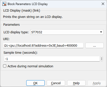
Display type
The type of LCD display.
Display mode
The display mode to use: text or image. In text mode, the LCD Display block prints strings to the display. In image mode it draws an image. Not all displays support image mode.
URI (tunable offline)
The URI indicating the protocol with which to communicate with the LCD display. Refer to Universal Resource Identifiers for more information about URIs and the communications protocols supported by QUARC.
Suitable URIs for the built-in LCD displays on the following platforms are listed below:
|
Platform |
Display Type |
URI |
Modes |
Characters |
Pixels |
Color |
|---|---|---|---|---|---|---|
|
QCar |
ST7032 |
i2c-cpu://localhost:8?address=0x3E,baud=400000 |
Text only |
2 x 16 |
N/A |
Black and white |
|
QBot 3 |
ST7066U |
serial://qbot3:0?baud=921600,device='/dev/qbot3_lcd' |
Text only |
2 x 16 |
N/A |
Black and white |
|
QCar2 |
LS027B7DH01 |
spi://localhost:1?word='8',baud='45000000',polarity='on',phase='on',memsize='8192',frame='0' |
Text or image |
12 x 25 |
240 x 400 |
Black and white |
|
QDrone2 |
LS012B7DD01 |
spi://localhost:2?word=8,baud=1000000,frame=1,memsize=990 |
Text or image |
2 x 16 |
38 x 184 |
Black and white |
|
QBot Platform |
WS0010 |
lcd://qbot_platform:1 |
Text or image |
2 x 16 |
16 x 100 |
Black and white |
|
Windows |
Quanser Mechatronics Sensors Trainer USB LCD |
lcd://localhost:0 |
Text or image |
24 x 50 |
480 x 800 |
RGB |
On Windows, with a Quanser QPIDe data acquisition card, for example, the WS0010 display can be used with the URI spi://localhost:0?baud=2e6,word=10,polarity=1,phase=1,frame=56 on the SPI pins of the control header.
Sample time
The sample time of the block. A sample time of 0 indicates that the block will be treated as a continuous time block. A positive sample time indicates that the block is a discrete time block with the given sample time.
A sample time of -1 indicates that the block inherits its sample time from the input. The block inherits the sample time by default.
To set the sample time to the fundamental sampling time of the model, use the qc_get_step_size function, which is a QUARC function that returns the fundamental sampling time of the model. The fundamental sampling time of the model is the sampling time entered in the Fixed step size field of the Solver pane of the Configuration parameters dialog.
Output sample time
The sample time of the block outputs when a touch screen is selected. An output sample time of 0 indicates that the outputs will be treated as continuous time. A positive sample time indicates that the outputs have a discrete sample time of the specified value. A discrete sample time of 1 / 120 (120 Hz) is the default.
An output sample time of -1 indicates that the outputs inherit their sample time.
To set the output sample time to the fundamental sampling time of the model, use the qc_get_step_size function, which is a QUARC function that returns the fundamental sampling time of the model. The fundamental sampling time of the model is the sampling time entered in the Fixed step size field of the Solver pane of the Configuration parameters dialog.
Use dark mode (tunable offline)
Indicates whether to use "dark mode" i.e., to use white text on a black background instead of black text on a white background. Not all displays support dark mode. Dark mode may be less efficient than normal mode.
Rotate display (tunable offline)
Indicates whether to rotate the display 180 degrees.
Active during normal simulation (tunable offline)
Indicates whether this block should execute during normal simulation. If this option is not checked then the block will not print to the LCD display during normal simulation. Note that the LCD display must be connected to the host PC to drive the display during normal simulation so this option is usually unchecked.
Targets
|
Target Name |
Compatible* |
Model Referencing |
Comments |
|---|---|---|---|
|
Yes |
Yes |
||
|
Yes |
Yes |
||
|
Yes |
Yes |
||
|
Yes |
Yes |
||
|
Yes |
Yes |
||
|
Yes |
Yes |
||
|
Yes |
Yes |
||
|
Yes |
Yes |
||
|
Yes |
Yes |
||
|
Yes |
Yes |
||
|
Yes |
Yes |
||
|
Yes |
Yes |
||
|
Yes |
Yes |
||
|
Yes |
Yes |
Last fully supported in QUARC 2018. |
|
|
Rapid Simulation (RSIM) Target |
Yes |
Yes |
|
|
S-Function Target |
No |
N/A |
Old technology. Use model referencing instead. |
|
Normal simulation |
Yes |
Yes |
See Also
Copyright ©2026 Quanser Inc. This page was generated 2026-05-13. Submit feedback to Quanser about this page.
Link to this page.