
Quanser Mechatronic Actuators Trainer
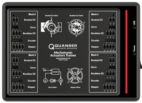
The Quanser Mechatronic Actuators Trainer is an integrated motor experiment. It is designed to help teach fundamental control concepts and theories on an easy-to-use and intuitive platform. For more information, visit Quanser Mechatronic Actuators Trainer
The Quanser Mechatronic Actuators Trainer provides the following capabilities:
The QUARC driver name for this card is mech_actuators_trainer_usb.
To select the Quanser Mechatronic Actuators Trainer HIL board, select the QUARC mech_actuators_trainer_usb board type from the drop-down list on the Main tab of the HIL Initialize block.
The Quanser Mechatronic Actuators Trainer I/O channels are described below.
Configuration
Each Quanser Mechatronic Actuators Trainer comprises of 4 identical blocks (block numbered 0 to 3) that allows the control of 4 different sets of motors at the same time.
Each block are independently addressed via separate HIL Initialize blocks.
To specify which Quanser Mechatronic Actuators Trainer board/device and block to be used, set the Board identifier parameter on
the Main tab using the x.y convention,
where x indicates the Quanser Mechatronic Actuators Trainer board/device
that is being addressed (typically it is 0 indicating the first Quanser Mechatronic Actuators Trainer connected to the system. Subsequent Quanser Mechatronic Actuators Trainers
are numbered sequentially, thus the second Quanser Mechatronic Actuators Trainer is 1), and y indicates the block number on that
particular Quanser Mechatronic Actuators Trainer that is being used.
For example, if trying to use block 2 of the first Quanser Mechatronic Actuators Trainer connected to the system.
The Board identifier parameter should be set as
0.2
Note that if only one number is specified (i.e. x. is omitted, then the number is interpreted as indicating
the block number. This is useful if there is only one Quanser Mechatronic Actuators Trainer connected to the system.
Clocks
The Quanser Mechatronic Actuators Trainer card does not support hardware clocks.
Analog Inputs
Each Quanser Mechatronic Actuators Trainer block supports 12 analog inputs. Hence, analog input channel numbers range from 0 to 11. The analog inputs are enumerated in the table below:
|
Channel |
Description |
Units |
|---|---|---|
|
0 |
Power supply current |
(A) |
|
1 |
Power supply voltage |
(V) |
|
2 |
Servo motor current |
(A) |
|
3 |
DC motor current |
(A) |
|
4 |
BLDC motor Channel A current |
(A) |
|
5 |
BLDC motor Channel B current |
(A) |
|
6 |
BLDC motor Channel C current |
(A) |
|
7 |
BLDC motor Channel A voltage |
(V) |
|
8 |
BLDC motor Channel B voltage |
(V) |
|
9 |
BLDC motor Channel C voltage |
(V) |
|
10 |
Stepper motor Channel A current |
(A) |
|
11 |
Stepper motor Channel B current |
(A) |
Analog Outputs
The Quanser Mechatronic Actuators Trainer card does not support analog outputs.
Digital Inputs
Each Quanser Mechatronic Actuators Trainer block supports 18 digital inputs. Hence, digital input channel numbers range from 0 to 17. The digital inputs are enumerated in the table below:
|
Channel |
Description |
|---|---|
|
0 |
Hall sensor A. Corresponds to pin A of encoder connector. |
|
1 |
Hall sensor B. Corresponds to pin B of encoder connector. |
|
2 |
Hall sensor C. Corresponds to pin C of encoder connector. |
|
3 |
Power supply voltage too low. Motor outputs in all blocks would be disabled and power LED would turn red. Power cycle the device to recover. |
|
4 |
Power supply voltage too high. Motor outputs in all blocks would be disabled and power LED would turn red. Power cycle the device to recover. |
|
5 |
Power supply current too high. Motor outputs in all blocks would be disabled and power LED would turn red. Power cycle the device to recover. |
|
6 |
DC motor current too high. Motor outputs in the corresponding block would be disabled and block LED would turn red. Toggle the DC motor enable signal in Digital Outputs to recover. |
|
7 |
DC motor current over-current/temperature. |
|
8 |
Servo motor supply current too high. Motor outputs in the corresponding block would be disabled and block LED would turn red. Toggle the Servo motor enable signal in Digital Outputs to recover. |
|
9 |
Servo motor supply voltage out of range. |
|
10 |
BLDC motor Channel A current too high. Motor outputs in the corresponding block would be disabled and block LED would turn red. Toggle the BLDC motor enable signal in Digital Outputs to recover. Note that in sensorless BLDC mode, all 3 BLDC channels should be toggled together to recover the device. |
|
11 |
BLDC motor Channel B current too high. Motor outputs in the corresponding block would be disabled and block LED would turn red. Toggle the BLDC motor enable signal in Digital Outputs to recover. Note that in sensorless BLDC mode, all 3 BLDC channels should be toggled together to recover the device. |
|
12 |
BLDC motor Channel C current too high. Motor outputs in the corresponding block would be disabled and block LED would turn red. Toggle the BLDC motor enable signal in Digital Outputs to recover. Note that in sensorless BLDC mode, all 3 BLDC channels should be toggled together to recover the device. |
|
13 |
Stepper motor Channel A winding current too high. Motor outputs in the corresponding block would be disabled and block LED would turn red. Toggle the Stepper motor enable signal in Digital Outputs to recover. |
|
14 |
Stepper motor Channel B winding current too high. Motor outputs in the corresponding block would be disabled and block LED would turn red. Toggle the Stepper motor enable signal in Digital Outputs to recover. |
|
15 |
Stepper motor Channel A driver over-current/temperature. |
|
16 |
Stepper motor Channel B driver over-current/temperature. |
|
17 |
Device over-temperature. Motor outputs in all blocks would be disabled and power LED would turn orange. Power cycle the device to recover. |
Digital Outputs
Each Quanser Mechatronic Actuators Trainer block supports 7 digital outputs, which corresponds to channel 0 to 6. The digital outputs act as enable for the motor drive circuitries. When output is low, the motor amplifier is disabled. When it is high, the motor amplifier is enabled.
The Quanser Mechatronic Actuators Trainer has internal safety detection and once an error is asserted (via Digital Inputs, the amplifier is automatically disables itself. The block can be re-enabled by setting the output low then high again.
| Note: Constantly resetting the amplifier whenever an error occurs can result in excessive heat being generated by the motor potentially causing damage. |
The full suite of digital outputs are enumerated in the following table:
|
Channel |
Description |
|---|---|
|
0 |
Servo motor power enable |
|
1 |
DC motor power enable |
|
2 |
BLDC motor A power enable |
|
3 |
BLDC motor B power enable |
|
4 |
BLDC motor C power enable |
|
5 |
Stepper motor A power enable |
|
6 |
Stepper motor B power enable |
Encoder Inputs
Each Quanser Mechatronic Actuators Trainer block supports one encoder input. The channel provide 24-bit count values. The encoder channel supports 2X, 4X quadrature mode. The encoder channels are enumerated in the table below:
|
Channel |
Description |
|---|---|
|
0 |
Encoder 0 position (can be used on any motor with encoder output) |
In order to set the encoder counters to a particular count when the model is loaded, the encoder inputs must
be configured on the HIL Initialize
block's Encoder Inputs tab. Set the Encoder input channels
field to all the encoder channels that will be
used on the board for the current diagram. For example, enter
0:1
to
indicate channels 0 through 1 are used as encoder inputs.
The first two encoder inputs are sampled simultaneously when measured using a single HIL Read block.
PWM Outputs
Each Quanser Mechatronic Actuators Trainer block driver supports up to 10 PWM output channels. Hence, PWM output channels range from 0 to 9. Each PWM channel is completely independent and can have its own duty cycle and frequency.
The PWM mode, frequency or configurations are fixed and cannot be modified.
The PWM channels are enumerated in the table below:
|
Channel |
Description |
|---|---|
|
0 |
Servo motor |
|
1 |
DC motor A |
|
2 |
DC motor B |
|
3 |
BLDC motor A |
|
4 |
BLDC motor B |
|
5 |
BLDC motor C |
|
6 |
Stepper motor A+ |
|
7 |
Stepper motor A- |
|
8 |
Stepper motor B+ |
|
9 |
Stepper motor B- |
Other Inputs
Each Quanser Mechatronic Actuators Trainer block supports three other input channels, as enumberated in the table below:
|
Channel |
Description |
Units |
|---|---|---|
|
10000 |
Device temperature |
(°C) |
|
14000 |
32-bit digital tachometer for encoder 0 velocity in counts/sec |
(counts/sec) |
|
14001 |
32-bit sensorless tachometer for BLDC motor in counts/sec |
(counts/sec) |
Channel numbers for Other Input or Output channels use predefined ranges for each type of measurement to ensure consistency between data acquisition devices. Refer to QUARC Other Channels for a list of the Other Input or Output channel number ranges defined for any HIL Data Acquisition Card and their SI units.
Other Outputs
The Quanser Mechatronic Actuators Trainer card does not support other outputs.
Interrupts
The Quanser Mechatronic Actuators Trainer card, or its driver, does not support any interrupt sources.
Watchdog
Each Quanser Mechatronic Actuators Trainer block supports a watchdog timer for resetting the outputs on watchdog expiry. Namely, the analog, digital and other output channels will be reset to the user-defined values on watchdog expiry. Resetting of the outputs occurs without software intervention, and therefore may be used as a safety mechanism in the event of software failure.
To enable the watchdog, place a HIL Watchdog block in the diagram.
To configure the values to which the output channels are reset on watchdog expiry, set the corresponding fields in the Analog Outputs, Digital Outputs and Other Outputs tabs of the HIL Initialize block.
Once the watchdog has expired, further I/O on the outputs is disabled until the watchdog state is cleared.
Use a HIL Watchdog Clear block to clear the watchdog state when the model is running. Restarting the model will also clear the watchdog state.
Board-Specific Options
Each Quanser Mechatronic Actuators Trainer block has a number of board-specific options to control specialized functionality of the card and compensate for nonlinear factors to create a near-ideal motor response.
supply_voltage_low_limit
This option sets low limit where the supply voltage drops below would trigger the supply_voltage_low_limit=10.
supply_voltage_high_limit
This option sets high limit where the supply voltage goes beyond would trigger the supply_voltage_high_limit=16.
supply_current_high_limit
This option sets high limit where the supply current goes beyond would trigger the supply_current_high_limit=8.
dc_motor_current_high_limit
This option sets high limit where the DC motor current goes beyond would trigger the dc_motor_current_high_limit=1.1.
servo_motor_current_high_limit
This option sets high limit where the Servo motor current goes beyond would trigger the servo_motor_current_high_limit=1.3.
bldc_motor_current_high_limit
This option sets high limit where the BLDC motor current goes beyond would trigger the bldc_motor_current_high_limit=2.
stepper_motor_current_high_limit
This option sets high limit where the Stepper motor current goes beyond would trigger the stepper_motor_current_high_limit=1.7.
servo_pwm_range
This option sets the PWM output pulse width on servo connector. Set this option to
servo_pwm_range=0 (default) for 0.5ms to 2.5ms range, and servo_pwm_range=1
for 1ms to 2ms range.
enc_dir
Set this option to "yes", "y" or "1" to reverse the direction of encoder. This feature makes it easier to use Quanser Mechatronic Actuators Trainer with different encoders where the direction of the encoder counts might be in reverse.
The default value is enc_dir=0.
bldc_motor_mode
Defines how the BLDC motor is derived. Set this option to bldc_motor_mode=0 (default)
for direct PWM drive used in sensored mode of operation. In this mode, all 3 BLDC motor outputs
(A, B and C) are directly derived by PWM channels 3,
4 and 5, and enabled by
3 BLDC motor enables (digital outputs 2,
3 and 4).
Set bldc_motor_mode=1 for sensorless mode of operation.
In this mode, only a single PWM output is used (PWM channel 3)
as a bidirectional I/O to drive the BLDC motor. Also in this mode, only a single BLDC enable (digital
output channel 2) is used to enable the motor.
bldc_start_tc
A parameter used only in sensorless BLDC mode of operation (bldc_motor_mode=1). This
parameter defines (in seconds) how fast BLDC reaches the desired speed during the start phase of
sensorless operation. The default value is bldc_start_tc=0.03.
bldc_start_target
A parameter used only in sensorless BLDC mode of operation (bldc_motor_mode=1). This
parameter defines (in RPM) the desired rotation speed reached in start phase of sensorless operation.
The default value is bldc_start_target=1200.
Properties
The Quanser Mechatronic Actuators Trainer driver currently supports the following read-only properties:
|
Property |
Type |
Description |
|---|---|---|
|
PROPERTY_INTEGER_VENDOR_ID |
Integer |
Vendor identifier associated with the hardware |
|
PROPERTY_INTEGER_PRODUCT_ID |
Integer |
Product identifier associated with the hardware |
|
PROPERTY_INTEGER_FIRMWARE_MAJOR_VERSION |
Integer |
Major version number of the firmware (hardware) |
|
PROPERTY_INTEGER_FIRMWARE_MINOR_VERSION |
Integer |
Minor version number of the firmware (Qube interface) |
|
PROPERTY_INTEGER_FIRMWARE_BUILD |
Integer |
Build number of the firmware (currently always zero) |
|
PROPERTY_INTEGER_HARDWARE_VERSION |
Integer |
Revision number of the firmware (currently always zero) |
|
PROPERTY_INTEGER_NUMBER_OF_ANALOG_INPUTS |
Integer |
The number of analog input channels. |
|
PROPERTY_INTEGER_NUMBER_OF_ENCODER_INPUTS |
Integer |
The number of encoder input channels. |
|
PROPERTY_INTEGER_NUMBER_OF_DIGITAL_INPUTS |
Integer |
The number of potential digital input channels. |
|
PROPERTY_INTEGER_NUMBER_OF_OTHER_INPUTS |
Integer |
The number of other input channels. |
|
PROPERTY_INTEGER_NUMBER_OF_ANALOG_OUTPUTS |
Integer |
The number of analog output channels. |
|
PROPERTY_INTEGER_NUMBER_OF_PWM_OUTPUTS |
Integer |
The number of PWM output channels. |
|
PROPERTY_INTEGER_NUMBER_OF_DIGITAL_OUTPUTS |
Integer |
The number of potential digital output channels. |
|
PROPERTY_INTEGER_NUMBER_OF_OTHER_OUTPUTS |
Integer |
The number of other output channels. |
|
PROPERTY_INTEGER_NUMBER_OF_CLOCKS |
Integer |
The number of clocks. |
|
PROPERTY_INTEGER_NUMBER_OF_INTERRUPTS |
Integer |
The number of interrupt channels. |
|
PROPERTY_INTEGER_IS_SIMULATION |
Integer |
Whether the device is a simulated device (1) or actual device (0). |
|
PROPERTY_STRING_MANUFACTURER |
String |
Manufacturer of the device |
|
PROPERTY_STRING_PRODUCT_NAME |
String |
Product name of the device |
|
PROPERTY_STRING_MODEL_NAME |
String |
Model name of the device |
|
PROPERTY_STRING_SERIAL_NUMBER |
String |
Serial number of the device |
|
PROPERTY_STRING_FIRMWARE_VERSION |
String |
Firmware version of the PC interface |
Connectors
The Quanser Mechatronic Actuators Trainer has a number of connectors for motors and encoders. These connectors and their pinouts are listed below. Note that there are 4 blocks on each device, each block has identical connectors. Therefore only one block's connectors are listed.
Brushed DC Connector
B ← | 2 |
A ← | 1 |
Servo Connector
- ― | 3 |
+ ― | 2 |
S ← | 1 |
Brushless DC Connector
C ← | 3 |
B ← | 2 |
A ← | 1 |
Encoder Connector
- ― | 5 |
C → | 4 |
A → | 3 |
+ ― | 2 |
B → | 1 |
Stepper Connector
B- ← | 4 |
B+ ← | 3 |
A- ← | 2 |
A+ ← | 1 |
Legend
→▯← | = | input |
←▯→ | = | output |
= | 5V signal | |
= | unspecified voltage | |
= | power | |
= | ground |
Targets
|
Target |
Supported |
Comments |
|---|---|---|
|
Yes |
Fully supported. |
|
|
Yes |
Fully supported. |
|
|
No |
Not supported. |
|
|
No |
Not supported. |
|
|
No |
Not supported. |
|
|
No |
Not supported. |
|
|
No |
Not supported. |
|
|
No |
Not supported. |
|
|
Yes |
Fully supported. |
|
|
No |
Not supported. |
|
|
No |
Not supported. |
|
|
No |
Not supported. |
|
|
No |
Not supported. |
|
|
No |
Not supported. |
|
|
No |
Last fully supported in QUARC 2018. |
|
|
Rapid Simulation (RSIM) Target |
Yes |
Supported with no communication to the hardware. |
|
Normal simulation |
Yes |
Supported with no communication to the hardware. |
See Also
Copyright ©2026 Quanser Inc. This page was generated 2026-05-13. Submit feedback to Quanser about this page.
Link to this page.
