
QArm-USB
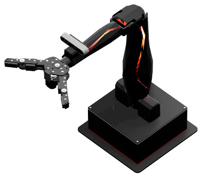
The QArm-USB is a 4 DOF serial robotic manipulator with a tendon-based two-stage gripper and an RGBD camera, designed specifically for modern engineering education. For more information, visit the Quanser website for the QArm.
The RCP Toolkit driver name for this card is qarm_usb.
The QArm-USB I/O channels are described below.
Clocks
There are currently no configuration options for the QArm-USB clocks.
Analog Inputs
The QArm-USB currently supports 10 analog inputs.
The first five analog inputs measure the voltage on the respective Analog Input pins found on the End Effector board's User Connector 1 (labelled AX, where X = {0,1,2,3,4}). The analog input range for these channels is 0 to +5V and is not configurable. Exceeding this range may damage the board.
The last five analog inputs measure the current to each servo motor joint in Amperes. Refer to the table below for a list of all analog input channels and their respective maximum ranges:
|
Channel |
Description |
Range |
|---|---|---|
|
0 |
User Analog Input 0 |
0V to +5V |
|
1 |
User Analog Input 1 |
0V to +5V |
|
2 |
User Analog Input 2 |
0V to +5V |
|
3 |
User Analog Input 3 |
0V to +5V |
|
4 |
User Analog Input 4 |
0V to +5V |
|
5 |
Present Current - Yaw Joint |
±4.4A |
|
6 |
Present Current - Shoulder Joint |
±8.8A |
|
7 |
Present Current - Elbow Joint |
±4.4A |
|
8 |
Present Current - Wrist Joint |
±2.3A |
|
9 |
Present Current - Gripper |
±1.4A |
Analog Outputs
The QArm-USB card does not support analog outputs.
Digital Inputs
The QArm-USB supports 18 bidirectional digital I/O lines. Hence digital input channel numbers range from 0 to 17. Digital lines are available on both User Connector 1 and User Connector 2 found on the End Effector board (labelled DX, where X = {0, ..., 17}). A digital I/O line cannot be used as an input and output at the same time.
| All digital input channels are 5V tolerant. Exceeding this voltage may damage the board. |
The first 18 digital I/O lines may be individually programmed as inputs or outputs on the QArm-USB.
All of those 18 channels which will be used for digital inputs should be configured on the
HIL Initialize VI's Digital Inputs tab.
Set the Digital input channels field to all the digital I/O channels that will be used as digital
inputs on the board for the current diagram. For example, enter 0:3 to designate channels 0 through 3 as
digital inputs. Specify [0, 4, 5] to indicate that channels 0, 4 and 5 are to be configured as digital inputs.
Digital Outputs
The QArm-USB supports 18 bidirectional digital I/O lines and one relay control. Hence digital output channel numbers range from 0 to 18. Digital lines 0-17 are available on both User Connector 1 and User Connector 2 found on the End Effector board (labelled DX, where X = {0, ..., 17}). A digital I/O line cannot be used as an input and output at the same time.
| All digital output channels are 3.3V. |
The relay control (channel 18) enables/disables the +12V, 1.5A supply found on the End Effector board. By default, the 12V supply is disabled to prevent accidentally shorting 12V to other pins.
Since the first 18 digital I/O lines may be individually programmed as inputs or outputs
on the QArm-USB, all the channels which will be used for digital outputs should be configured
on the HIL Initialize VI's
Digital Outputs tab. Set the Digital output channels
field to all the bidirectional digital I/O channels that will
be used as digital outputs on the board for the current diagram. For example, enter
0:3 to designate channels 0 through 3 as digital outputs. Specify
[0, 4, 5] to indicate that channels 0, 4 and 5 are to be configured
as digital outputs.
To set the digital output values when the block diagram is run or stopped, set the Initial digital outputs and Final digital outputs to the desired values respectively.
Encoder Inputs
The QArm-USB supports one quadrature encoder input with a 16-bit count value. Hence the only valid encoder input channel number is 0. This channel only supports 4X quadrature mode. Valid initial count values range from -32,768 to +32,767. Encoder channel 0 is available on User Connector 1 found on the End Effector board. The encoder inputs are shared with digital I/O lines 0 and 1.
In order to set the encoder counters to a particular count when the model is loaded, the encoder inputs must be configured on the HIL Initialize VI's Encoder Inputs tab.
The encoder inputs are sampled simultaneously when measured using a single HIL Read VI.
The QArm-USB sign convention in quadrature (4X) mode increments the encoder counter value when the channel 2 signal leads the channel 1 signal. Conversely, the encoder counter value is decreased when channel 1 leads channel 2.
PWM Outputs
The QArm-USB driver supports up to 3 PWM output channels. Hence, PWM output channels range from 0 to 2. Each PWM channel is completely independent and can have its own duty cycle and frequency. The PWM outputs are shared with digital I/O lines 7, 8 and 9.
These three channels are driven by independent timebases so they may operate at different frequencies and in different modes. The PWM base frequencies can range from 0.0167638Hz up to 36MHz. The resolution of your PWM can be as high as 16-bits or as low as 1-bit depending on the selected frequency. Use the PWM configuration wizard (the "..." button to the right of any of the active PWM fields on the PWM Outputs tab) to get more information about what resolution you will get at what frequencies.
The PWM output channels support mode 0 (duty cycle, fixed frequency), mode 3 (one-shot, fixed frequency) and mode 4 (active pulse time, fixed frequency). All three modes will only update after a given cycle is complete to ensure "glitchless" transitions. Therefore, for slow base frequencies, it may take several samples of your model before the update is seen on the output. RC servos for instance typically run with a period of 20ms, so a 1ms controller may need to wait up to 20 samples before the desired output is observed.
To set the PWM output values when the watchdog expires, set the PWM outputs on watchdog expiry to states to match the channel assignments in the PWM output channels field.
Other Inputs
The QArm-USB currently supports 20 other input channels, which are enumerated in the table below. SI units are used.
|
Channel |
Description |
|---|---|
|
1000 |
Angular Position in rad - Yaw Joint |
|
1001 |
Angular Position in rad - Shoulder Joint |
|
1002 |
Angular Position in rad - Elbow Joint |
|
1003 |
Angular Position in rad - Wrist Joint |
|
1004 |
Angular Position as a percentage - Gripper (0.0 to 1.0 representing 0% to 100%, with 0% = fully open and 100% = fully closed) |
|
3000 |
Angular Velocity in rad/s - Yaw Joint |
|
3001 |
Angular Velocity in rad/s - Shoulder Joint |
|
3002 |
Angular Velocity in rad/s - Elbow Joint |
|
3003 |
Angular Velocity in rad/s - Wrist Joint |
|
3004 |
Angular Velocity as a percentage of the no-load speed (0.0 to ±1.0 representing 0% to 100%) - Gripper |
|
10000 |
Temperature in °C - Yaw Joint |
|
10001 |
Temperature in °C - Shoulder Joint |
|
10002 |
Temperature in °C - Elbow Joint |
|
10003 |
Temperature in °C - Wrist Joint |
|
10004 |
Temperature in °C - Gripper |
|
11000 |
Present PWM reading as a percentage (0.0 to ±1.0 representing 0% to 100%) - Yaw Joint |
|
11001 |
Present PWM reading as a percentage (0.0 to ±1.0 representing 0% to 100%) - Shoulder Joint |
|
11002 |
Present PWM reading as a percentage (0.0 to ±1.0 representing 0% to 100%) - Elbow Joint |
|
11003 |
Present PWM reading as a percentage (0.0 to ±1.0 representing 0% to 100%) - Wrist Joint |
|
11004 |
Present PWM reading as a percentage (0.0 to ±1.0 representing 0% to 100%) - Gripper |
Other Outputs
The QArm-USB currently supports 14 other output channels. The first 5 channels control the angular position of each joint that is operating in Position Mode. The next channels control the PWM value of each joint that is operating in PWM Mode. The remaining 4 channels control the brightness of the R, G and B LEDs, as well as the red LEDs along the arm. Refer to the table below for a list of the channels. SI units are used.
|
Channel |
Description |
Range |
|---|---|---|
|
1000 |
Angular Position in rad - Yaw Joint |
±3 |
|
1001 |
Angular Position in rad - Shoulder Joint |
±ℼ/2 |
|
1002 |
Angular Position in rad - Elbow Joint |
-1.74, +1.39 |
|
1003 |
Angular Position in rad - Wrist Joint |
±3 |
|
1004 |
Angular Position as a percentage - Gripper |
0.0 to 1.0 representing 0% to 100%, with 0% = fully open and 100% = fully closed |
|
11000 |
Goal PWM value of the Yaw joint as a percentage. |
0.0 to ±1.0 (representing 0% to 100%) |
|
11001 |
Goal PWM value of Shoulder joint as a percentage. |
0.0 to ±1.0 (representing 0% to 100%) |
|
11002 |
Goal PWM value of Elbow joint as a percentage. |
0.0 to ±1.0 (representing 0% to 100%) |
|
11003 |
Goal PWM value of Wrist joint as a percentage. |
0.0 to ±1.0 (representing 0% to 100%) |
|
11004 |
Goal PWM value of the Gripper motor as a percentage. |
0.0 to ±1.0 (representing 0% to 100%) |
|
11005 |
Red component of the base LED panel as a percentage. |
0.0 to 1.0 (representing 0% to 100%) |
|
11006 |
Green component of the base LED panel as a percentage. |
0.0 to 1.0 (representing 0% to 100%) |
|
11007 |
Blue component of the base LED panel as a percentage. |
0.0 to 1.0 (representing 0% to 100%) |
|
11008 |
Red LEDs along the bicep and forearm as a percentage. |
0.0 to 1.0 (representing 0% to 100%) |
Interrupts
The QArm-USB card, or its driver, does not support any interrupt sources.
Watchdog
The QArm-USB supports a watchdog timer for resetting the outputs on watchdog expiry. Namely, the digital, PWM and other output channels will be reset to the user-defined values on watchdog expiry. Resetting of the outputs occurs without software intervention, and therefore may be used as a safety mechanism in the event of software failure.
To enable the resetting of the analog or digital, check the Set output on watchdog options on the respective tabs of the HIL Initialize VI parameters dialog. Set the Output on watchdog expiry fields to the desired values. Then place a CL HIL Watchdog VI in the diagram.
Once the watchdog has expired, further output is disabled until the watchdog state is cleared. Hence, in RCP, the outputs will remain in the watchdog state even after the VI is stopped, unless a CL HIL Watchdog Clear VI is used to clear the watchdog state. Restarting the VI will automatically clear the watchdog.
Board-Specific Options
The QArm-USB has a number of board-specific options to control specialized functionality of the arm. These options configure the operating mode and trajectory profile of each joint.
Each joint can be individually configured in the board-specific options by selecting its numerical designator and replacing the X variable in the approriate option name with this designator. The Gripper simply uses the designator gripper. See the table below for the enumerated designator values.
|
Joint |
Value |
|---|---|
|
Yaw |
0 |
|
Shoulder |
1 |
|
Elbow |
2 |
|
Wrist |
3 |
jX_mode, gripper_mode
This option configures the operating mode of each joint. The valid values can be found in the table below.
|
Operating Mode |
Value |
|---|---|
|
Position Mode |
0 |
|
PWM Mode |
1 |
| When operating any of the joints in PWM Mode, you will be using the QArm-USB at your own risk! Please proceed with caution. |
jX_profile_config, gripper_profile_config
This option sets the base for the appropriate joint's trajectory profile. Valid values are 0 and 1, where 0 selects a Velocity-based profile and 1 selects a Time-based profile.
| Note that the profile configuration is only applied to joints operating in Position Mode. |
jX_profile_velocity, gripper_profile_velocity
This option sets the maximum velocity or time span of the appropriate joint's trajectory profile, depending on the base selected in the profile configuration option mentioned above. For a Velocity-based profile, valid values range from 0.0 rad/s to 785.0 rad/s. A value of 0 sets no limit to the maximum velocity. For a Time-based profile, valid values range from 0.0 s to 32.7 s.
| Note that the profile velocity is only applied to joints operating in Position Mode. |
| For maximum joint velocities exceeding ℼ/2 rad/s, you will be using the QArm-USB at your own risk! Please proceed with caution. |
jX_profile_acceleration, gripper_profile_acceleration
This option sets the maximum acceleration or accelerating time of the appropriate joint's trajectory profile, depending on the base selected in the profile configuration option mentioned above. For a Velocity-based profile, valid values range from 0.0 rad/s2 to 12271.0 rad/s2. A value of 0 sets no limit the maximum acceleration. For a Time-based profile, valid values range from 0.0 s to 32.7 s.
| Note that the profile acceleration is only applied to joints operating in Position Mode. |
| For maximum joint accelerations exceeding ℼ/3 rad/s2, you will be using the QArm-USB at your own risk! Please proceed with caution. |
Properties
The QArm-USB driver currently supports a number of double properties used to tune the internal Position Controller gains found in the joint servo motors.
| Note the double properties are only applied to joints operating in Position Mode. |
The double properties are enumerated in the table below.
|
Description |
Property Value |
Range |
|---|---|---|
|
Position P Gain - Yaw Joint |
128 |
0.0 - 127.0 |
|
Position P Gain - Shoulder Joint |
129 |
0.0 - 127.0 |
|
Position P Gain - Elbow Joint |
130 |
0.0 - 127.0 |
|
Position P Gain - Wrist Joint |
131 |
0.0 - 127.0 |
|
Position I Gain - Yaw Joint |
133 |
0.0 - 0.24 |
|
Position I Gain - Shoulder Joint |
134 |
0.0 - 0.24 |
|
Position I Gain - Elbow Joint |
135 |
0.0 - 0.24 |
|
Position I Gain - Wrist Joint |
136 |
0.0 - 0.24 |
|
Position D Gain - Yaw Joint |
138 |
0.0 - 1023.0 |
|
Position D Gain - Shoulder Joint |
139 |
0.0 - 1023.0 |
|
Position D Gain - Elbow Joint |
140 |
0.0 - 1023.0 |
|
Position D Gain - Wrist Joint |
141 |
0.0 - 1023.0 |
|
Feedforward Velocity Gain - Yaw Joint |
143 |
0.0 - 4095.0 |
|
Feedforward Velocity Gain - Shoulder Joint |
144 |
0.0 - 4095.0 |
|
Feedforward Velocity Gain - Elbow Joint |
145 |
0.0 - 4095.0 |
|
Feedforward Velocity Gain - Wrist Joint |
146 |
0.0 - 4095.0 |
|
Feedforward Acceleration Gain - Yaw Joint |
148 |
0.0 - 4095.0 |
|
Feedforward Acceleration Gain - Shoulder Joint |
149 |
0.0 - 4095.0 |
|
Feedforward Acceleration Gain - Elbow Joint |
150 |
0.0 - 4095.0 |
|
Feedforward Acceleration Gain - Wrist Joint |
151 |
0.0 - 4095.0 |
The QArm-USB driver also supports the following read-only properties:
|
Property |
Type |
Description |
|---|---|---|
|
PROPERTY_INTEGER_VENDOR_ID |
Integer |
Vendor identifier associated with the hardware |
|
PROPERTY_INTEGER_PRODUCT_ID |
Integer |
Product identifier associated with the hardware |
|
PROPERTY_INTEGER_FIRMWARE_MAJOR_VERSION |
Integer |
Major version number of the firmware (hardware) |
|
PROPERTY_INTEGER_FIRMWARE_MINOR_VERSION |
Integer |
Minor version number of the firmware (QArm interface) |
|
PROPERTY_INTEGER_FIRMWARE_BUILD |
Integer |
Build number of the firmware (currently always zero) |
|
PROPERTY_INTEGER_FIRMWARE_REVISION |
Integer |
Revision number of the firmware |
|
PROPERTY_STRING_MANUFACTURER |
String |
Manufacturer of the device |
|
PROPERTY_STRING_PRODUCT_NAME |
String |
Product name of the device |
|
PROPERTY_STRING_MODEL_NAME |
String |
Model name of the device |
|
PROPERTY_STRING_SERIAL_NUMBER |
String |
Serial number of the device |
|
PROPERTY_STRING_FIRMWARE_VERSION |
String |
Firmware version of the PC interface |
Targets
|
Target |
Supported |
Comments |
|---|---|---|
|
Yes |
Fully supported |
See Also
Copyright © Quanser Inc. This page was generated 2024-11-15. Submit feedback to Quanser about this page.
Link to this page.
