
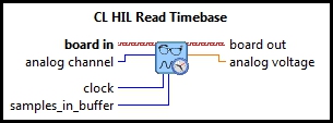
CL HIL Read Timebase Analog (Scalar)
| Parent Polymorphic VI: | CL HIL Read Timebase |
| Requirements: | Quanser Rapid Control Prototyping Toolkit, LabVIEW 2022 or newer, Control Design and Simulation Module |
Description
Reads from an analog input channel of a HIL board while establishing the timing of the simulation loop via a hardware timebase.
Required Inputs  All required inputs must be wired. They always appear as terminals on the VI palette. They also appear in bold text in the context help window for the VI.

|
board in is a reference to a HIL Board instance that represents the open HIL board. This input must be wired to a valid HIL Board signal, as generated by a HIL Initialize VI. |
Recommended Inputs or Dialog Box Options
Recommended inputs need not to be wired. They may be selected to appear as terminals or dialog parameters, but show up as terminals by default.
They appear in simple text in the context help window for the VI.

|
analog channel is a channel number indicating the analog input channel to be read. The voltage (or current) read will appear at the analog voltage output. |

|
clock indicates which hardware timer on the HIL board is to be used as the timebase for the Simulation loop. For most applications, the default clock of zero is appropriate. Refer to the documentation for a specific HIL board for more details on the clocks available on that board. |
|
|
samples in buffer determines the size of the hardware interrupt queue. Hardware interrupts generated by the timer on the HIL board are queued until they are processed by the application. This parameter dictates the size of that queue. Many cards only support a buffer size of one. Large buffer sizes are useful on soft real-time systems to allow the occasional sample to be lost if the application can tolerate it (particularly at startup). |
Outputs

|
board out is a copy of the HIL Board instance passed to the board in input. |

|
analog voltage is the analog voltage (or current) read from the specified analog channel. |
Details
This VI only reads one analog input. When reading from mixed signal types, it is more efficient to use the
This VI employs a hardware timebase on the data acquisition card to drive the timing of the Simulation loop. The clock parameter determines which timebase on the board is used. The Simulation loop should be configured so that it is not synchronized to a timing source. Also, the priority of the application VI should be set to time-critical. The priority is found in the VI Properties under the Execution category.
Feedthrough Behaviour
All input/output pairs of this function have direct feedthrough behaviour.
Examples
| RCP CL HIL Read Timebase Example |
Targets
|
Target |
Supported |
Comments |
|---|---|---|
|
Yes |
Fully supported. |
Copyright © Quanser Inc. This page was generated 2024-11-15. Submit feedback to Quanser about this page.
Link to this page.