MATLAB Command Line
Click to copy the following command line to the clipboard. Then paste it in the MATLAB Command Window:
quarc_spi_lcd_display_demoQUARC SPI LCD Display Demo
This is a more complex example of using an SPI device with QUARC. It interfaces with an NHD-C12832A1Z-FSW-FBW-3V3 Chip-On-Glass Liquid Crystal Display Module. It also demonstrates how to use Atomic Subsystems MATLAB Command Line Click to copy the following command line to the clipboard. Then paste it in the MATLAB Command Window: doc('atomic subsystem'); to sequence hardware I/O and SPI communications.
It is important to note that with SPI communications there are no signals to indicate whether a read or write is being performed. With SPI communications, data is always read and written at the same time. Hence, every write operation results in the same amount of data being read. Thus, when using the Stream blocks to communicate using SPI, it is important to always perform the write first followed by a read of exactly the same number of bytes. A Stream Write-Read block may be used for this purpose, or separate Stream Write blocks followed by a Stream Read block which reads the same number of bytes as the number of bytes written. The Stream Read will not cause another SPI bus cycle because the data being read will already be in the stream receive buffer.
System Requirements
This demonstration is run using the QUARC for Windows or QUARC for Win64 target with a Quanser QPID or QPIDe data acquisition card for SPI support. This example may also be run on other SPI-capable QUARC targets, such as the QUARC Linux DuoVero Target on the QBot 2 or QBall 2. No QPID(e) card is required in that case. Note that a software license for the desired target is required.
To run on other QUARC targets supporting SPI, the appropriate HIL board will need to be selected, voltage levels will need to be checked (+3.3V required), and the port and frame option of the URI in the Stream Call block will likely need to be changed. Further details may be found below under the heading Running the example on a different target.
This example also requires an NHD-C12832A1Z-FSW-FBW-3V3 COG (Chip-On-Glass) Liquid Crystal Display Module from Newhaven Display International Inc., wired to SPI port 0 of the target. The example requires the following connections to the LCD module. Refer to the datasheet for details.
|
|
| Do not power the backlight (A) using a QPIDe digital I/O pin. The backlight voltage cannot exceed +3.0V and the QPIDe digital I/O are +3.3V. Furthermore, the QPIDe digital I/O do not have the drive strength required to power the LCD backlight. |
The VDD power (as opposed to the backlight) should be provided by a separate isolated +3.3V supply. Be sure to connect the ground of the supply to DGND. If a +3.3V supply is not available, then the QPIDe DIO2 pin may be used. However, this solution is not recommended as the overall current capability of a bank of digital outputs is limited.
For information on programming the LCD module via the SPI interface, refer to the Sitronix ST7565R datasheet.
Configuring the Demonstration
The URI used by the Stream Call block determines the baud rate and other options used for SPI communications. The options have been configured to match those required by the NHD-C12832A1Z-FSW-FBW-3V3 device and should not be changed. The baud rate, however, may be modified but should never be faster than 20 MHz (20e6) which is the limit for the NHD-C12832A1Z-FSW-FBW-3V3 device.
To change the URI of the Stream Call block, double-click on the block to open its configuration dialog, as shown below.
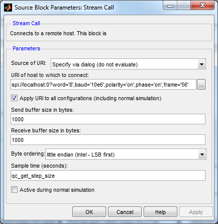
In the URI of host to which to connect field, replace the value of the baud option in the URI with the desired baud rate. If the example is being run on a target other than Windows then the port number and frame option may need to be changed as well. See the SPI Protocol documentation for details on the format of the URI.
Click OK to close the configuration dialog.
Running the Model Using the QUARC Target for Windows
Please note that in order to be able to run this part of the demo, you must have purchased the QUARC Target for Windows as part of your license. In addition you must have satisfied the software and hardware requirements found in the QUARC Installation Guide.
To open the model click on the "Open this model" button found on the top right corner of this page.
Select from the menu of the diagram, or select from the simulation mode combo box on the toolbar.
Select from the menu of the diagram, or press Ctrl+B while the diagram is the active window. A great deal of output will appear in the Diagnostic Viewer about the progress of the build. If you cannot see the Diagnostic Viewer, you can open it by selecting from the menu of the diagram, or clicking on the View Diagnostics hyperlink at the bottom of the diagram. If you have MATLAB R2013b or earlier then the output will appear in the MATLAB Command Window.
If the build is successful, then the line:
*** Created executable quarc_spi_lcd_display_demo.rt-win64
will appear in the Diagnostic Viewer. Finally, QUARC will download the model to the QUARC Target for Windows. The line:
### Model quarc_spi_lcd_display_demo has been downloaded to target 'shmem://quarc-target:1' (440320 bytes)
will appear in the Diagnostic Viewer indicating that the code was successfully downloaded to the QUARC Target. If any errors occur, appropriate error messages will appear in the Diagnostic Viewer.
Make sure the Select image or animation Manual Switch is up (toward the static image branch).
Click on the button or select from the menu of the diagram to connect to the model.
Start the model by clicking on the button or selecting from the menu of the diagram. The item of the menu may also be used to both connect and start the model in one operation.
An image of a fish will appear on the LCD display as depicted below:

Double-click on the Select image or animation Manual Switch to set it in the downward position (toward the animation branch). A stick man will walk across the LCD display. See the video to see what it looks like.
Click on the button or select from the menu of the diagram to stop the model. The item of the menu may also be used.
Running the example on a different target
To run the example on a different target, refer to the instructions on the Running QUARC Examples on Remote Targets page.
The HIL Initialize block parameters should be modified
to use a card supported on the given target. For example, for the QBot 2, the qbot2 driver should be selected. For
the QBall 2, the qball2 card should be chosen. The following settings on the Digital Outputs tab should also
be configured. Note that the HIL Initialize block saves the settings configured for every card so settings are not
lost when changing cards.
|
Field |
Value |
|---|---|
|
Digital output channels |
[0:2] |
|
Initial digital outputs |
[0 0 1] |
|
Final digital outputs |
[0] |
The URI of the Stream Call block must also be changed to suit the particular target. Below are sample URIs for different QUARC targets that support SPI:
|
Target |
Port |
Chip Select |
URI |
|---|---|---|---|
|
QUARC Windows Target with QPID(e) |
0 |
SS |
spi://localhost:0?word='8',baud='10e6',polarity='on',phase='on',frame='56' |
|
QUARC Win64 Target with QPID(e) |
0 |
SS |
spi://localhost:0?word='8',baud='10e6',polarity='on',phase='on',frame='56' |
|
QUARC Linux DuoVero Target on QBot 2 |
1 |
CS0 |
spi://localhost:1?word='8',baud='10e6',polarity='on',phase='on',frame='0' |
|
QUARC Linux DuoVero Target on QBall 2 |
1 |
CS0 |
spi://localhost:1?word='8',baud='10e6',polarity='on',phase='on',frame='0' |
When wiring the LCD module on a different target, use the same wiring diagram but replace the QPIDe with the equivalent I/O on the target platform. The table above shows the SPI port and chip select to use for some sample targets.
Copyright ©2026 Quanser Inc. This page was generated 2026-05-13. Submit feedback to Quanser about this page.
Link to this page.
