
Quanser Mechatronics Sensors Trainer USB Knob Encoder Page
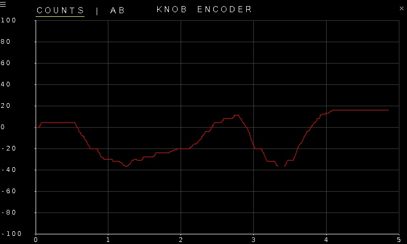
The Quanser Mechatronics Sensors Trainer USB Knob Encoder Page plots the knob encoder counts or A and B quadrature signals. The signal to be plotted may be selected from the COUNTS or AB options in the top, left of the plot. By default it plots the encoder counts. The page is displayed below with a sample plot, showing the knob encoder counts in red.
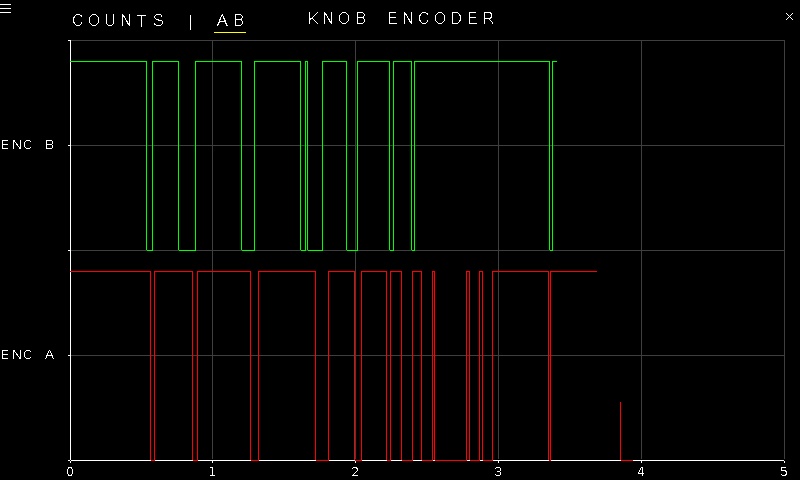
When the AB option is selected, the plot looks like this instead, where the red line is the encoder A signal and the green line is the encoder B signal. The A and B signals are the raw signals that the encoder uses to generate the quadrature encoder counts. Since the knob may be moved quite slowly, it provides an opportunity to better understand these raw signals.
To go back to the Sensors page, tap on the close button in the top, right corner of the page. To change the sensor parameters, tap on the hamburger menu in the top, left corner of the page. This will open the settings screen described in the section below.
The encoder A and B signals are digital signals. The plot axes are fixed, even though the encoder counts could potentially exceed the limits of the range.
Settings
The settings page is illustrated below.
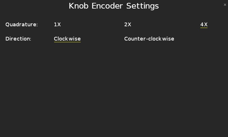
The Quadrature parameter allows the knob encoder to be configured for 1X, 2X or 4X quadrature. Full quadrature, or 4X, is typically used with an encoder.
The Direction parameter allows the polarity of the knob encoder to be changed so that clockwise rotation results in positive encoder counts or counterclockwise rotation results in positive encoder counts.
Tap the close button in the top, right of the page to apply the new settings and return to the plot.
Copyright ©2026 Quanser Inc. This page was generated 2026-05-13. Submit feedback to Quanser about this page.
Link to this page.