
Quanser Mechatronics Sensors Trainer USB External Encoder Page
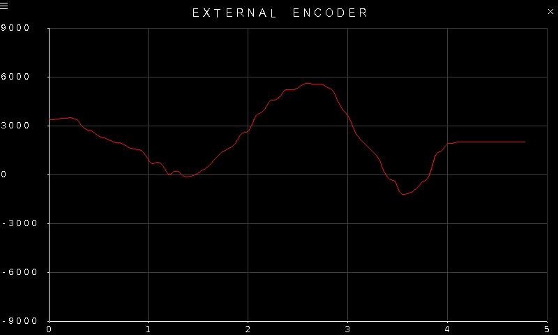
The Quanser Mechatronics Sensors Trainer USB External Encoder Page plots the external encoder counts. The A and B signals are not available because the external encoder tends to have much higher resolution and so plotting the A and B signals does not provide valuable insight on the device itself. The page is displayed below with a sample plot, showing the external encoder counts in red.
To go back to the Sensors page, tap on the close button in the top, right corner of the page. To change the sensor parameters, tap on the hamburger menu in the top, left corner of the page. This will open the settings screen described in the section below.
The plot axes are fixed, even though the encoder counts could potentially exceed the limits of the range.
Settings
The settings page is illustrated below.
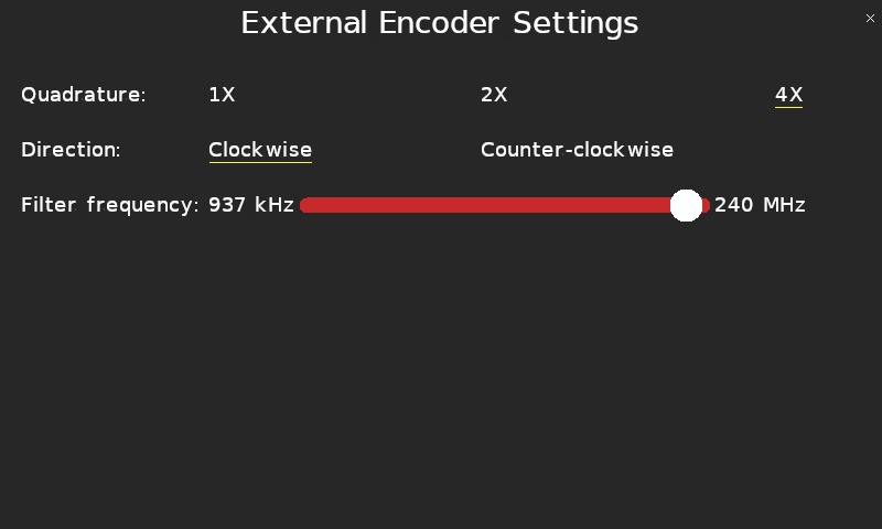
The Quadrature parameter allows the external encoder to be configured for 1X, 2X or 4X quadrature. Full quadrature, or 4X, is typically used with an encoder.
The Direction parameter allows the polarity of the external encoder to be changed so that clockwise rotation results in positive encoder counts or counterclockwise rotation results in positive encoder counts.
Since the external encoder supports much higher rates, the encoder supports a filter to deal with noise on the encoder A and B signal lines. The filter frequency may be configured using the Filter frequency slider, which supports filter frequencies ranging from 537 kHz to 240 MHz.
Tap the close button in the top, right of the page to apply the new settings and return to the plot.
Copyright ©2026 Quanser Inc. This page was generated 2026-05-13. Submit feedback to Quanser about this page.
Link to this page.