
Quanser Mechatronics Sensors Trainer USB Digital and Analog I/O Page
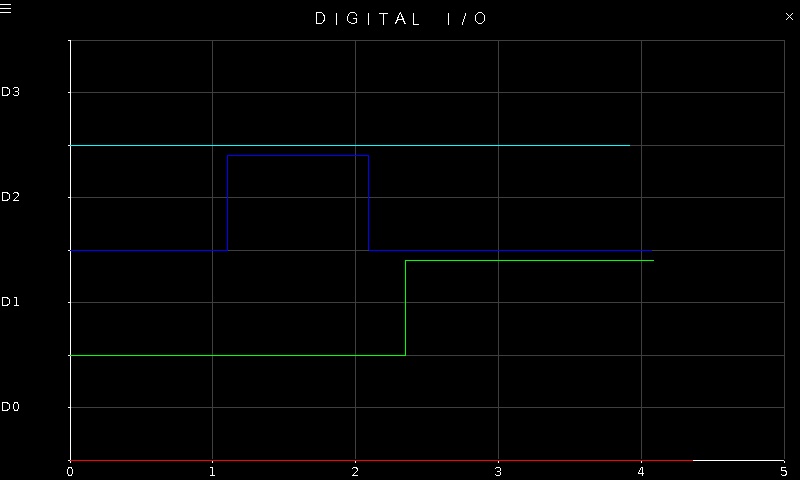
The Quanser Mechatronics Sensors Trainer USB Digital and Analog I/O Page plots the values of the digital I/O D0 to D3 on the user header. However, these four inputs can also be configured as analog inputs or digital outputs and the last two digital I/O may be configured as PWM output signals. This page can plot any of these options, which may be configured on the settings page described in the section below. For example, the page is displayed below with a sample plot where all four inputs are configured as digital inputs, showing D0 in red, D1 in green, D2 in blue and D3 in cyan.
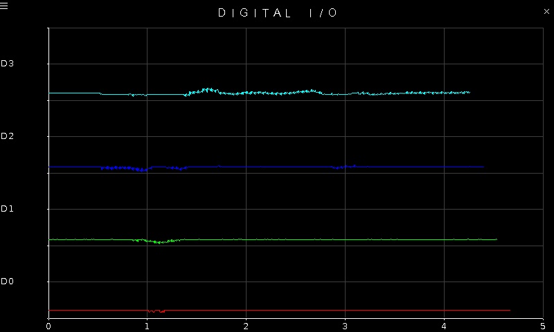
When all four inputs are configured as analog inputs, the plot may look more like the following:
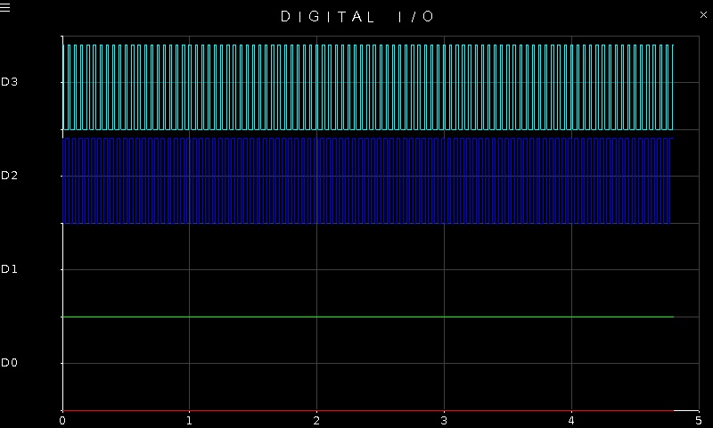
Note that the inputs may be configured as analog or digital inputs in any combination. It is not necessary for all the inputs to be analog or all the inputs to be digital at the same time. One or more of them may even be digital or PWM outputs. For example, the figure below shows what the plot may look like if the last two channels are configured as PWM outputs:
To go back to the Sensors page, tap on the close button in the top, right corner of the page. To change the sensor parameters, tap on the hamburger menu in the top, left corner of the page. This will open the settings screen described in the section below.
The plot axes are fixed, regardless how the I/O are configured.
Settings
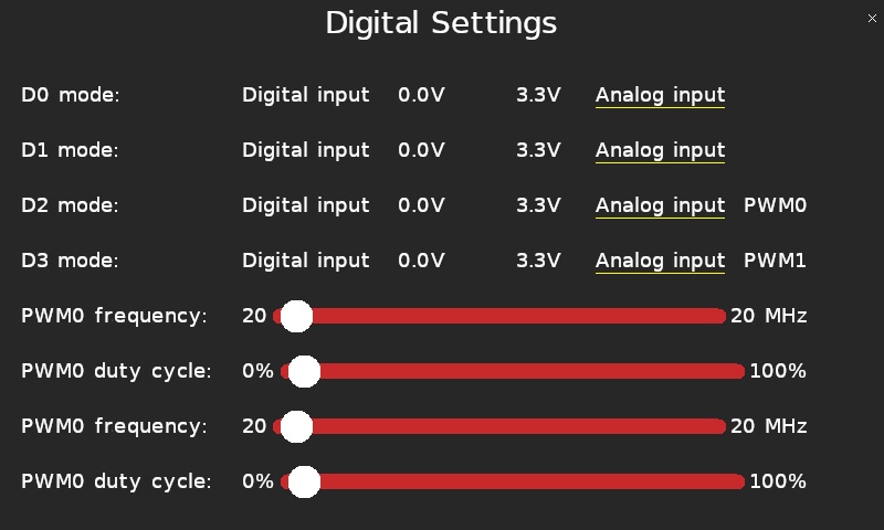
The settings page is illustrated below with all channels configured as digital inputs.
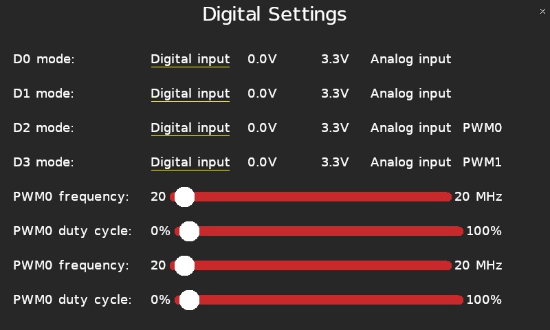
The D0 mode, D1 mode, D2 mode and D3 mode parameters configure the D0, D1, D2 and D3 pins respectively. Each pin may be configured as a digital input, or as a digital output driven to ground (0.0V), or as a digital output driven to VCC (3.3V), or as an analog input.
The settings page is depicted below with all channels configured as analog inputs.
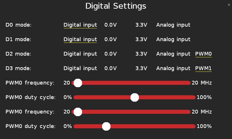
The last two pins, D2 and D3, may also be configured as PWM outputs (PWM0 and PWM1 respectively). The frequency and duty cycle of these PWM outputs may be set using the PWM0 frequency and PWM0 duty cycle sliders for PWM0 (D2), and the PWM1 frequency and PWM1 duty cycle sliders for PWM1 (D3). If the frequency is set but the duty cycle remains at 0% or 100% then the signal will be low or high respectively, without any visible variation. Be aware that the PWM outputs will likely show aliasing in the plots because the plot sampling frequency is relatively low.
The settings page is pictured below with the last two channels configured as PWM outputs.
Tap the close button in the top, right of the page to apply the new settings and return to the plot.
Copyright ©2026 Quanser Inc. This page was generated 2026-05-13. Submit feedback to Quanser about this page.
Link to this page.